
R2511-HP MSR Router Series Layer 2 - LAN Switching Configuration Guide(V5)

22
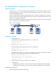
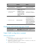
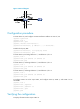
Figure 7 Network diagram
Configuration procedure
# Create VLAN 10, and configure its VLAN interface IP address as 10.0.0.1/24.
<Sysname> system-view
[Sysname] vlan 10
[Sysname-vlan10] quit
[Sysname] interface vlan-interface 10
[Sysname-Vlan-interface10] ip address 10.0.0.1 255.255.255.0
# Enable local proxy ARP.
[Sysname-Vlan-interface10] local-proxy-arp enable
[Sysname-Vlan-interface10] quit
# Create VLAN 2, and assign Ethernet 1/1 and Ethernet 1/2 to it.
[Sysname] vlan 2
[Sysname-vlan2] port ethernet 1/1 ethernet 1/2
[Sysname-vlan2] quit
# Create VLAN 3, and assign Ethernet 1/3 and Ethernet 1/4 to it.
[Sysname] vlan 3
[Sysname-vlan3] port ethernet 1/3 ethernet 1/4
[Sysname-vlan3] quit
# Create VLAN 5, and assign Ethernet 1/5 and Ethernet 1/6 to it.
[Sysname] vlan 5
[Sysname-vlan5] port ethernet 1/5 ethernet 1/6
[Sysname-vlan5] quit
# Configure VLAN 10 as the super VLAN, and configure VLAN 2, VLAN 3, and VLAN 5 as its
sub-VLANs.
[Sysname] vlan 10
[Sysname-vlan10] supervlan
[Sysname-vlan10] subvlan 2 3 5
[Sysname-vlan10] quit
[Sysname] quit
Verifying the configuration
# Display information about super VLAN 10.