
R2511-HP MSR Router Series Layer 2 - LAN Switching Configuration Guide(V5)

45
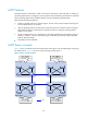
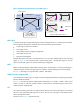
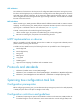
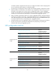
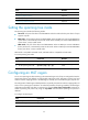
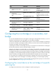
Figure 16 Network diagram and topology of MST region 3
MST region
A multiple spanning tree region (MST region) consists of multiple devices in a switched network and the
network segments among them. All these devices have the following characteristics:
• A spanning tree protocol is enabled.
• Same region name.
• Same VLAN-to-instance mapping configuration.
• Same MSTP revision level.
• Physically linked together.
Multiple MST regions can exist in a switched network. You can assign multiple devices to the same MST
region. In Figure 15,
the switched network comprises MST region 1 through MST region 4, and all
devices in each MST region have the same MST region configuration.
MSTI
MSTP can generate multiple independent spanning trees in an MST region, and each spanning tree is
mapped to specific VLANs. Each spanning tree is called a "multiple spanning tree instance (MSTI)."
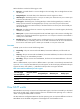
In Figure 16, M
ST region 3 comprises MSTI 1, MSTI 2, and MSTI 0.
VLAN-to-instance mapping table
As an attribute of an MST region, the VLAN-to-instance mapping table describes mapping relationships
between VLANs and MSTIs.
In Figure 16, the VL
AN-to-instance mapping table of MST region 3 is: VLAN 1 to MSTI 1, VLAN 2 and
VLAN 3 to MSTI 2, and other VLANs to MSTI 0. MSTP achieves load balancing by means of the
VLAN-to-instance mapping table.
CST
The common spanning tree (CST) is a single spanning tree that connects all MST regions in a switched
network. If you regard each MST region as a device, the CST is a spanning tree calculated by these
devices through STP or RSTP.
The blue lines in Figure 15 r
epresent the CST.
MST region 3
Device A
Device C
Device B
Device D
VLAN 1 MSTI 1
VLAN 2&3
MSTI 2
Other VLANs
MSTI 0
To MST region 4
To MST region 2
BA
C D
MSTI 1
A B
C D
MSTI 0
B
D
MSTI 2
C
A
Regional root
MSTI
Topology of MSTIs in MST region 3