
R2511-HP MSR Router Series Layer 2 - LAN Switching Configuration Guide(V5)

55
Configuring the maximum hops of an MST region
By setting the maximum hops of an MST region, you can restrict the region size. The maximum hops
configured on the regional root bridge will be used as the maximum hops of the MST region.
Configuration BPDUs sent by the regional root bridge always have a hop count set to the maximum value.
When a device receives this configuration BPDU, it decrements the hop count by 1 and uses the new hop
count in BPDUs that it propagates. When the hop count of a BPDU reaches 0, it is discarded by the
device that received it. This prevents devices beyond the reach of the maximum hop from participating in
spanning tree calculation, so the size of the MST region is limited.
Make this configuration on the root bridge only. All other devices in the MST region use the maximum
hop value set for the root bridge.
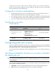
To configure the maximum number of hops of an MST region:
Step Command Remarks
1. Enter system view.
system-view N/A
2. Configure the maximum hops
of the MST region.
stp max-hops hops The default setting is 20.
Configuring the network diameter of a switched
network
Any two terminal devices in a switched network are connected through a specific path composed of a
series of devices. The network diameter is the number of devices on the path composed of the most
devices. The network diameter is a parameter that indicates the network size. A bigger network diameter
indicates a larger network size. Based on the network diameter you configured, the system automatically
sets an optimal hello time, forward delay, and max age for the device.
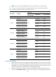
To configure the network diameter of a switched network:
Step Command Remarks
1. Enter system view.
system-view N/A
2. Configure the network
diameter of the switched
network.
stp bridge-diameter diameter The default setting is 7.
In STP, RSTP, or MSTP mode, each MST region is considered as a device and the configured network
diameter is effective only on the CIST (or the common root bridge), but not on other MSTIs.
Configuring spanning tree timers
The following timers are used for spanning tree calculations:
• Forward delay—The delay time for port state transition. To prevent temporary loops on a network,
the spanning tree sets an intermediate port state, the learning state, before it transits from the
discarding state to the forwarding state. The port transits its state after a forward delay timer expires,
to make sure the state transition of the local port remains synchronized with the peer.