
R2511-HP MSR Router Series Layer 2 - LAN Switching Configuration Guide(V5)

72
Task Command Remarks
Display MST region configuration
information in effect.
display stp region-configuration [ |
{ begin | exclude | include }
regular-expression ]
Available in any
view.
Display root bridge information for all
MSTIs.
display stp root [ | { begin | exclude |
include } regular-expression ]
Available in any
view.
Clear spanning tree statistics. reset stp [ interface interface-list ]
Available in user
view.
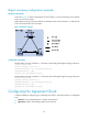
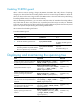
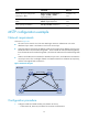
MSTP configuration example
Network requirements
As shown in Figure 22:
• All routers on the network are in the same MST region. Router A and Router B work at the
distribution layer. Router C and Router D work at the access layer.
• Configure MSTP so that packets of different VLANs are forwarded along different spanning trees:
Packets of VLAN 10 are forwarded along MSTI 1, those of VLAN 30 are forwarded along MSTI 3,
those of VLAN 40 are forwarded along MSTI 4, and those of VLAN 20 are forwarded along MSTI
0.
• VLAN 10 and VLAN 30 are terminated on distribution layer routers, and VLAN 40 is terminated on
access layer routers. The root bridges of MSTI 1 and MSTI 3 are Router A and Router B, respectively,
and the root bridge of MSTI 4 is Router C.
Figure 22 Network diagram
Configuration procedure
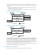
1. Configure VLANs and VLAN member ports (details not shown):
{ Create VLAN 10, VLAN 20, and VLAN 30 on Router A and Router B.
Permit: all VLAN
P
e
r
mi
t
:
V
L
A
N
2
0
,
3
0
P
e
r
mi
t
:
V
L
A
N
1
0
,
2
0
Permit: VLAN 20, 40
Permit: VLAN 20, 30Permit: VLAN 10, 20
Router A Router B
Router C Router D
Eth1/3
E
t
h
1
/
2
Eth1/3
E
t
h
1
/
2
Eth1/3 Eth1/3
E
t
h
1
/
2
E
t
h
1
/
2
MST region