
R2511-HP MSR Router Series Layer 2 - LAN Switching Configuration Guide(V5)

91
Layer 2 static aggregation configuration example
Network requirements
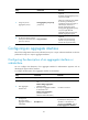
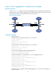
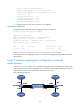
As shown in Figure 27, configure a Layer 2 static aggregation group on both Router A and Router B.
Enable VLAN 10 at one end of the aggregate link to communicate with VLAN 10 at the other end, and
VLAN 20 at one end to communicate with VLAN 20 at the other end.
Figure 27 Network diagram
Configuration procedure
1. Configure Router A:
# Create VLAN 10, and assign port Ethernet 1/4 to VLAN 10.
<RouterA> system-view
[RouterA] vlan 10
[RouterA-vlan10] port ethernet 1/4
[RouterA-vlan10] quit
# Create VLAN 20, and assign port Ethernet 1/5 to VLAN 20.
[RouterA] vlan 20
[RouterA-vlan20] port ethernet 1/5
[RouterA-vlan20] quit
# Create Layer 2 aggregate interface Bridge-Aggregation 1.
[RouterA] interface bridge-aggregation 1
[RouterA-Bridge-Aggregation1] quit
# Assign ports Ethernet 1/1 through Ethernet 1/3 to link aggregation group 1.
[RouterA] interface ethernet 1/1
[RouterA-Ethernet1/1] port link-aggregation group 1
[RouterA-Ethernet1/1] quit
[RouterA] interface ethernet 1/2
[RouterA-Ethernet1/2] port link-aggregation group 1
[RouterA-Ethernet1/2] quit
[RouterA] interface ethernet 1/3
[RouterA-Ethernet1/3] port link-aggregation group 1
[RouterA-Ethernet1/3] quit
# Configure Layer 2 aggregate interface Bridge-Aggregation 1 as a trunk port and assign it to
VLANs 10 and 20.