
R2511-HP MSR Router Series Layer 3 - IP Routing Configuration Guide(V5)


107
[RouterA-ospf-1] filter-policy 2000 import
[RouterA-ospf-1] quit
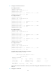
# Display the OSPF routing table of Router A.
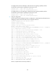
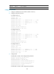
[RouterA] display ip routing-table
Routing Tables: Public
Destinations : 10 Routes : 10
Destination/Mask Proto Pre Cost NextHop Interface
3.1.1.0/24 O_ASE 150 1 10.2.1.2 Eth1/2
3.1.2.0/24 O_ASE 150 1 10.2.1.2 Eth1/2
10.1.1.0/24 Direct 0 0 10.1.1.1 Eth1/1
10.1.1.1/32 Direct 0 0 127.0.0.1 InLoop0
10.2.1.0/24 Direct 0 0 10.2.1.1 Eth1/2
10.2.1.1/32 Direct 0 0 127.0.0.1 InLoop0
10.3.1.0/24 OSPF 10 4 10.1.1.2 Eth1/1
10.4.1.0/24 OSPF 10 13 10.2.1.2 Eth1/2
127.0.0.0/8 Direct 0 0 127.0.0.1 InLoop0
127.0.0.1/32 Direct 0 0 127.0.0.1 InLoop0
The route to 10.5.1.1/24 is filtered out.
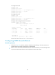
Configuring BFD for OSPF
Network requirements
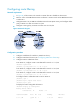
As shown in Figure 27:
• OSPF is enabled on Router A, Router B, and Router C so that they are reachable to each other at
the network layer.
• After the link over which Router A and Router B communicate through a Layer 2 switch fails, BFD
can quickly detect the failure and notify OSPF of the failure. Router A and Router B then
communicate through Router C.
Figure 27 Network diagram
Device Interface IP address
Device
Interface
IP address
Router A Eth 1/1 192.168.0.102/24
Router B Eth 1/1 192.168.0.100/24
Eth
1/2 10.1.1.102/24
Eth
1/2
13.1.1.1/24