
R2511-HP MSR Router Series Layer 3 - IP Routing Configuration Guide(V5)


151
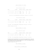
192.168.0.0/24 10 NULL S2/0 Direct D/L/-
10.1.1.0/24 20 NULL S2/0 192.168.0.1 R/-/-
10.1.2.0/24 20 NULL S2/0 192.168.0.1 R/-/-
172.16.0.0/16 10 NULL Eth1/1 Direct D/L/-
Flags: D-Direct, R-Added to RM, L-Advertised in LSPs, U-Up/Down Bit Set
DIS election configuration
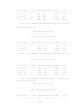
Network requirements
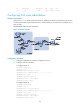
As shown in Figure 43, on a broadcast network (Ethernet), Router A, Router B, Router C, and Router D
reside in IS-IS area 10. Router A and Router B are Level-1-2 routers, Router C is a Level-1 router, and Router
D is a Level-2 router.
Change the DIS priority of Router A to make it elected as the Level-1-2 DIS router.
Figure 43 Network diagram
Configuration procedure
1. Configure an IP address for each interface. (Details not shown.)
2. Enable IS-IS:
# Configure Router A.
<RouterA> system-view
[RouterA] isis 1
[RouterA-isis-1] network-entity 10.0000.0000.0001.00
[RouterA-isis-1] quit
[RouterA] interface ethernet 1/1
[RouterA-Ethernet1/1] isis enable 1
[RouterA-Ethernet1/1] quit
# Configure Router B.
<RouterB> system-view
[RouterB] isis 1
[RouterB-isis-1] network-entity 10.0000.0000.0002.00
Router A
L1/L2
Router C
L1
Router B
L1/L2
Router D
L2
Eth1/1
10.1.1.1/24
Eth1/1
10.1.1.2/24
Eth1/1
10.1.1.3/24
Eth1/1
10.1.1.4/24