
R2511-HP MSR Router Series Layer 3 - IP Routing Configuration Guide(V5)


164
[RouterC-isis-1] network-entity 10.0000.0000.0003.00
[RouterC-isis-1] quit
[RouterC] interface ethernet 1/1
[RouterC-Ethernet1/1] isis enable
[RouterC-Ethernet1/1] quit
[RouterC] interface ethernet 1/2
[RouterC-Ethernet1/2] isis enable
[RouterC-Ethernet1/2] quit
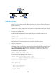
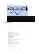
3. Configure BFD functions:
# Enable BFD on Router A and configure BFD parameters.
[RouterA] bfd session init-mode active
[RouterA] interface ethernet 1/1
[RouterA-Ethernet1/1] isis bfd enable
[RouterA-Ethernet1/1] bfd min-receive-interval 500
[RouterA-Ethernet1/1] bfd min-transmit-interval 500
[RouterA-Ethernet1/1] bfd detect-multiplier 7
# Enable BFD on Router B and configure BFD parameters.
[RouterB] bfd session init-mode active
[RouterB] interface ethernet 1/1
[RouterB-Ethernet1/1] isis bfd enable
[RouterB-Ethernet1/1] bfd min-receive-interval 500
[RouterB-Ethernet1/1] bfd min-transmit-interval 500
[RouterB-Ethernet1/1] bfd detect-multiplier 8
4. Verify the configuration:
The following configurations are made on Router A. Configurations for Router B are similar.
(Details not shown.)
# Display the BFD information of Router A.
<RouterA> display bfd session
Total Session Num: 1 Init Mode: Active
Session Working Under Ctrl Mode:
LD/RD SourceAddr DestAddr State Holdtime Interface
3/1 192.168.0.102 192.168.0.100 Up 1700ms Eth1/1
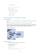
# Display route 120.1.1.0/24 on Router A, and you can see that Router A and Router B
communicate through the Layer-2 switch.
<RouterA> display ip routing-table 120.1.1.0 verbose
Routing Table : Public
Summary Count : 2
Destination: 120.1.1.0/24
Protocol: ISIS Process ID: 0
Preference: 0 Cost: 2
IpPrecedence: QosLcId:
NextHop: 192.168.0.100 Interface: Ethernet1/1
BkNextHop: 0.0.0.0 BkInterface:
RelyNextHop: 0.0.0.0 Neighbor : 0.0.0.0
Tunnel ID: 0x0 Label: NULL
BKTunnel ID: 0x0 BKLabel: NULL
State: Active Adv Age: 00h58m10s