
R2511-HP MSR Router Series Layer 3 - IP Routing Configuration Guide(V5)

222
PING 8.1.1.1: 56 data bytes, press CTRL_C to break
Reply from 8.1.1.1: bytes=56 Sequence=1 ttl=254 time=2 ms
Reply from 8.1.1.1: bytes=56 Sequence=2 ttl=254 time=2 ms
Reply from 8.1.1.1: bytes=56 Sequence=3 ttl=254 time=2 ms
Reply from 8.1.1.1: bytes=56 Sequence=4 ttl=254 time=2 ms
Reply from 8.1.1.1: bytes=56 Sequence=5 ttl=254 time=2 ms
--- 8.1.1.1 ping statistics ---
5 packet(s) transmitted
5 packet(s) received
0.00% packet loss
round-trip min/avg/max = 2/2/2 ms
BGP load balancing configuration
Network requirements
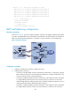
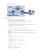
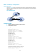
As shown in Figure 64, all routers run BGP, and Router A resides in AS 65008, and Router B and Router
C reside in AS 65009. EBGP runs between Router A and Router B, and between Router A and Router C.
IBGP runs between Router B and Router C. Configure two routes on Router A for load balancing.
Figure 64 Network diagram
Configuration procedure
1. Configure IP addresses for interfaces. (Details not shown.)
2. Configure BGP connections:
{ On Router A, establish EBGP connections with Router B and Router C, respectively; configure
B G P t o a dv e r t i s e n e t wo r k 8 .1.1. 0 / 24 t o Ro u t e r B and Router C, so Router B and Router C can
access the internal network connected to Router A.
{ On Router B, establish an EBGP connection with Router A and an IBGP connection with Router
C; configure BGP to advertise network 9.1.1.0/24 to Router A, so Router A can access the
intranet through Router B; configure a static route to interface loopback 0 on Router C (or use a
routing protocol like OSPF) to establish the IBGP connection.
{ On Router C, establish an EBGP connection with Router A and an IBGP connection with Router
B; configure BGP to advertise network 9.1.1.0/24 to Router A, so Router A can access the