
R2511-HP MSR Router Series Layer 3 - IP Routing Configuration Guide(V5)


13
[RouterA] ip route-static 120.1.1.0 24 ethernet 1/2 10.1.1.100 preference 65
[RouterA] quit
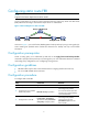
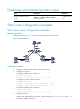
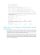
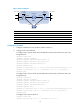
# Configure static routes on Router B and enable BFD control packet mode for the static route
through the Layer 2 switch.
<RouterB> system-view
[RouterB] interface ethernet 1/1
[RouterB-Ethernet1/1] bfd min-transmit-interval 500
[RouterB-Ethernet1/1] bfd min-receive-interval 500
[RouterB-Ethernet1/1] bfd detect-multiplier 9
[RouterB-Ethernet1/1] quit
[RouterB] ip route-static 121.1.1.0 24 ethernet 1/1 12.1.1.1 bfd control-packet
[RouterB] ip route-static 121.1.1.0 24 ethernet 1/2 13.1.1.2 preference 65
[RouterB] quit
# Configure static routes on Router C.
<RouterC> system-view
[RouterC] ip route-static 120.1.1.0 24 ethernet 1/2 13.1.1.1
[RouterC] ip route-static 121.1.1.0 24 ethernet 1/1 10.1.1.102
3. Verify the configuration:
# Display BFD sessions on Router A.
<RouterA> display bfd session
Total Session Num: 1 Init Mode: Active
Session Working Under Ctrl Mode:
LD/RD SourceAddr DestAddr State Holdtime Interface
4/7 12.1.1.1 12.1.1.2 Up 2000ms Ethernet1/1
The output shows that the BFD session has been created.
# Display static routes on Router A. The static route to Router B through the Layer 2 switch is
displayed in the output.
<RouterA> display ip routing-table protocol static
Public Routing Table : Static
Summary Count : 2
Static Routing table Status : <Active>
Summary Count : 1
Destination/Mask Proto Pre Cost NextHop Interface
120.1.1.0/24 Static 60 0 12.1.1.2 Eth1/1
Direct Routing table Status : <Inactive>
Summary Count : 1
Destination/Mask Proto Pre Cost NextHop Interface
120.1.1.0/24 Static 65 0 10.1.1.100 Eth1/2
# Enable BFD debugging. When the link between Router A and the switch fails, Router A can
detect the failure.