
R2511-HP MSR Router Series Layer 3 - IP Routing Configuration Guide(V5)


238
[RouterC-route-policy] quit
# Apply the routing policy localpref to the route from the peer 193.1.1.1 on Router C.
[RouterC] bgp 200
[RouterC-bgp] peer 193.1.1.1 route-policy localpref import
[RouterC-bgp] quit
# Display the BGP routing table on Router D.
[RouterD] display bgp routing-table
Total Number of Routes: 2
BGP Local router ID is 194.1.1.1
Status codes: * - valid, ^ - VPNv4 best, > - best, d - damped,
h - history, i - internal, s - suppressed, S - Stale
Origin : i - IGP, e - EGP, ? - incomplete
Network NextHop MED LocPrf PrefVal Path/Ogn
*>i 1.0.0.0 193.1.1.1 0 200 0 100i
* i 192.1.1.1 0 100 0 100i
The route 1.0.0.0/8 learned from Router C is the optimal.
BGP GR configuration
Network requirements
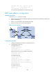
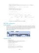
As shown in Figure 70, all routers run BGP. EBGP runs between Router A and Router B. IBGP runs
between router B and Router C. Router A and Router C are MSR routers, and Router B is a GR restarter
of another router model. Enable GR capability for BGP so that the communication between Router A and
Router C cannot be affected when an active/standby switchover occurs on Router B.
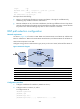
Figure 70 Network diagram
Configuration procedure
1. Configure Router A:
# Configure IP addresses for interfaces. (Details not shown.)
# Configure the EBGP connection.
<RouterA> system-view
[RouterA] bgp 65008
[RouterA-bgp] router-id 1.1.1.1
[RouterA-bgp] peer 200.1.1.1 as-number 65009
# Inject network 8.0.0.0/8 to the BGP routing table.
[RouterA-bgp] network 8.0.0.0