
R2511-HP MSR Router Series Layer 3 - IP Routing Configuration Guide(V5)
239
# Enable GR capability for BGP.
[RouterA-bgp] graceful-restart
2. Configure Router B:
# Configure IP addresses for interfaces. (Details not shown.)
# Configure the EBGP connection.
<RouterB> system-view
[RouterB] bgp 65009
[RouterB-bgp] router-id 2.2.2.2
[RouterB-bgp] peer 200.1.1.2 as-number 65008
# Configure the IBGP connection.
[RouterB-bgp] peer 9.1.1.2 as-number 65009
# Inject networks 200.1.1.0/24 and 9.1.1.0/24 to the BGP routing table.
[RouterB-bgp] network 200.1.1.0 24
[RouterB-bgp] network 9.1.1.0 24
# Enable GR capability for BGP.
[RouterB-bgp] graceful-restart
3. Configure Router C:
# Configure IP addresses for interfaces. (Details not shown.)
# Configure the IBGP connection.
<RouterC> system-view
[RouterC] bgp 65009
[RouterC-bgp] router-id 3.3.3.3
[RouterC-bgp] peer 9.1.1.1 as-number 65009
# Enable GR capability for BGP.
[RouterC-bgp] graceful-restart
Verifying the configuration
# Ping Router C on Router A. Meanwhile, perform an active/standby switchover on Router B. The ping
operation is successful during the whole switchover process.
Configuring BFD for BGP
Network requirements
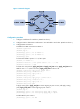
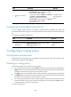
As shown in Figure 71,
• Configure OSPF as the IGP in AS 200.
• Establish two IBGP connections between Router A and Router C. When both links are working,
Router C adopts the link Router A<—>Router B<—>Router C to exchange packets with network
1.1.1.0/24. Configure BFD over the link. Then if the link fails, BFD can quickly detect the failure and
notify it to BGP. Then the link Router A<—>Router D<—>Router C takes effect immediately.