
R2511-HP MSR Router Series Layer 3 - IP Routing Configuration Guide(V5)


268
2. Configure Router B:
# Configure a static route to subnet 10.110.0.0/24.
<RouterB> system-view
[RouterB] ip route-static 10.110.0.0 24 1.1.2.1
# Configure the IP address of the serial interface.
[RouterB] interface serial 2/0
[RouterB-Serial2/0] ip address 1.1.2.2 255.255.255.0
3. Configure Router C:
# Configure a static route to subnet 10.110.0.0/24.
<RouterC> system-view
[RouterC] ip route-static 10.110.0.0 24 1.1.3.1
# Configure the IP address of the serial interface.
[RouterC] interface serial 2/1
[RouterC-Serial2/1] ip address 1.1.3.2 255.255.255.0
4. Verify the configuration:
Configure the IP address 10.110.0.20/24 for Host A, and specify its gateway address as
10.110.0.10.
On Host A, Telnet to Router B that is directly connected to Router A. The operation succeeds.
On Host A, Telnet to Router C that is directly connected to Router A. The operation fails.
Ping Router C from Host A. The operation succeeds.
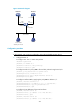
Telnet uses TCP, and ping uses ICMP. The preceding results show that all TCP packets received on
Ethernet 1/1 of Router A are forwarded through Serial 2/0, and other packets are forwarded
through Serial 2/1. The interface PBR configuration is effective.
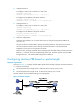
Configuring interface PBR based on packet length
Network requirements
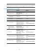
As shown in Figure 77, configure interface PBR to guide the forwarding of packets received on Ethernet
1/1 of Router A as follows:
• Forwards packets with a length of 64 to 100 bytes to the next hop 150.1.1.2/24.
• Forwards packets with a length of 101 t o 10 0 0 t o t h e n ex t h o p 151.1.1. 2 / 24 .
All other packets are forwarded according to the routing table.
Figure 77 Network diagram