
R2511-HP MSR Router Series Layer 3 - IP Routing Configuration Guide(V5)


271
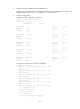
The debugging information about PBR displayed on Router A is as follows:
<RouterA>
*Jun 7 12:06:47:631 2009 RouterA PBR/7/POLICY-ROUTING: IP policy based routing
success : POLICY_ROUTEMAP : lab1, Node : 20, next-hop : 151.1.1.2
*Jun 7 12:06:48:630 2009 RouterA PBR/7/POLICY-ROUTING: IP policy based routing
success : POLICY_ROUTEMAP : lab1, Node : 20, next-hop : 151.1.1.2
*Jun 7 12:06:49:627 2009 RouterA PBR/7/POLICY-ROUTING: IP policy based routing
success : POLICY_ROUTEMAP : lab1, Node : 20, next-hop : 151.1.1.2
*Jun 7 12:06:50:627 2009 RouterA PBR/7/POLICY-ROUTING: IP policy based routing
success : POLICY_ROUTEMAP : lab1, Node : 20, next-hop : 151.1.1.2
The preceding information shows that Router A sets the next hop for the received packets to
151.1.1.2 according to PBR. The packets are forwarded through Serial 2/1.
Configuring local PBR to specify output interface and next hop
Network requirements
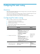
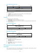
As shown in Figure 78:
• The downlink port of the router is connected to the hosts, and its uplink port Ethernet1/1 is
connected to the Internet.
• The subinterface Ethernet 1/1.1 obtains its IP address through DHCP.
Configure local PBR so that the router forward SNMP packets and SNMP traps through the subinterface
E t h e r n e t 1 / 1.1.
Figure 78 Network diagram
Configuration procedure
# Configure the subinterface Ethernet1/1.1 to obtain its IP address through DHCP.
<Router> system-view
[Router] interface ethernet 1/1.1
[Router-Ethernet1/1.1] ip address dhcp-alloc
[Router-Ethernet1/1.1] vlan-type dot1q vid 1
[Router-Ethernet1/1.1] quit
# Configure ACL 3000 to match SNMP packets and SNMP traps.
[Router] acl number 3000
[Router-acl-adv-3000] rule 0 permit udp source-port eq snmp
[Router-acl-adv-3000] rule 5 permit udp destination-port eq snmptrap
[Router-acl-adv-3000] quit