
R2511-HP MSR Router Series Layer 3 - IP Routing Configuration Guide(V5)


337
Configuring BFD for IPv6 IS-IS
Network requirements
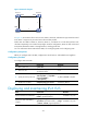
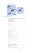
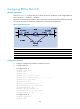
As shown in Figure 95, configure IPv6 IS-IS on Router A, Router B, and Router C and configure BFD over
the link Router A<—>L2 Switch<—>Router B.
When the link between Router B and the Layer-2 switch fails, BFD can quickly detect the failure and notify
IPv6 IS-IS of the failure. Then Router A and Router B communicate through Router C.
Figure 95 Network diagram
Device Interface IPv6 address Device Interface IPv6 address
Router A Eth1/1 2001::1/64
Router B
Eth1/1
2001::2/64
Eth1/2 2001:2::1/64
Eth1/2
2001:3::2/64
Router C Eth1/1 2001:2::2/64
Eth1/2 2001:3::1/64
Configuration procedure
1. Configure IP addresses for interfaces. (Details not shown.)
2. Configure IPv6 IS-IS:
# Configure Router A.
<RouterA> system-view
[RouterA] ipv6
[RouterA] isis 1
[RouterA-isis-1] is-level level-1
[RouterA-isis-1] network-entity 10.0000.0000.0001.00
[RouterA-isis-1] ipv6 enable
[RouterA-isis-1] quit
[RouterA] interface ethernet 1/1
[RouterA-Ethernet1/1] isis ipv6 enable 1
[RouterA-Ethernet1/1] quit
[RouterA] interface ethernet 1/2
[RouterA-Ethernet1/2] isis ipv6 enable 1
[RouterA-Ethernet1/2] quit
# Configure Router B.
<RouterB> system-view
[RouterB] ipv6