
R2511-HP MSR Router Series Layer 3 - IP Routing Configuration Guide(V5)

39
# On Router B, define ACL 2000 and reference it to a filtering policy to filter routes redistributed
from RIP 100, making the route not advertised to Router C.
[RouterB] acl number 2000
[RouterB-acl-basic-2000] rule deny source 10.2.1.1 0.0.0.255
[RouterB-acl-basic-2000] rule permit
[RouterB-acl-basic-2000] quit
[RouterB] rip 200
[RouterB-rip-200] filter-policy 2000 export rip 100
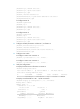
# Display the routing table on Router C.
[RouterC] display ip routing-table
Routing Tables: Public
Destinations : 7 Routes : 7
Destination/Mask Proto Pre Cost NextHop Interface
11.1.1.0/24 RIP 100 1 12.3.1.1 Eth1/1
12.3.1.0/24 Direct 0 0 12.3.1.2 Eth1/1
12.3.1.2/32 Direct 0 0 127.0.0.1 InLoop0
16.4.1.0/24 Direct 0 0 16.4.1.1 Eth1/2
16.4.1.1/32 Direct 0 0 127.0.0.1 InLoop0
127.0.0.0/8 Direct 0 0 127.0.0.1 InLoop0
127.0.0.1/32 Direct 0 0 127.0.0.1 InLoop0
Configuring an additional metric for a RIP interface
Network requirements
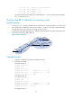
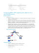
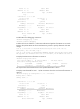
As shown in Figure 7, run RIPv2 is enabled on all the interfaces of Router A, Router B, Router C, Router
D, and Router E.
Router A has two links to Router D. The link from Router B to Router D is more stable than that from Router
C to Router D. Configure an additional metric for RIP routes received from Ethernet 1/2 on Router A so
Router A prefers route 1.1.5.0/24 learned from Router B.
Figure 7 Network diagram
Configuration procedure
1. Configure IP addresses for the interfaces. (Details not shown.)
2. Configure basic RIP:
# Configure Router A.
<RouterA> system-view
[RouterA] rip