
R2511-HP MSR Router Series Layer 3 - IP Services Configuration Guide(V5)

115
Configuration procedure
To configure IP virtual fragment reassembly:
Step Command Remarks
1. Enter system view.
system-view N/A
2. Enter interface view.
interface interface-type interface-number N/A
3. Enable IP virtual fragment
reassembly.
ip virtual-reassembly [ drop-fragments |
max-fragments number | max-reassemblies
number | timeout seconds ] *
By default, the feature is
disabled.
Configuration example
Network requirements
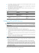
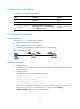
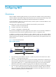
As shown in Figure 51, configure devices as follows:
• Router A connects to Host and Router B.
• NAT is enabled on Ethernet 1/2 of Router A.
• Configure IP virtual fragment reassembly on Ethernet 1/2 of Router A.
Figure 51 Network diagram
Configuration procedure
1. Configure the host:
# Configure a route so that the Host, Router A, and Router B can communicate with each other.
(Details not shown.)
2. Configure Router A:
# Configure NAT and IP virtual fragment reassembly.
<RouterA> system-view
[RouterA] nat static 10.1.1.1 11.2.2.3
[RouterA] interface ethernet 1/2
[RouterA-Ethernet1/2] nat outbound static
[RouterA-Ethernet1/2] ip virtual-reassembly
With the IP virtual fragment reassembly feature, Router A checks, sequences, and caches
fragments that do not arrive in order at Ethernet 1/2. You can use the display ip
virtual-reassembly command to view related information.