
R2511-HP MSR Router Series Layer 3 - IP Services Configuration Guide(V5)


151
2. Configure Router A on the IPv4 side:
# Configure a static route to subnet 9.0.0.0/24.
<RouterA> system-view
[RouterA] ip route-static 9.0.0.0 24 8.0.0.1
3. Configure Router C on the IPv6 side:
# Enable IPv6.
<RouterC> system-view
[RouterC] ipv6
# Configure a static route to the subnet with the NAT-PT prefix.
[RouterC] ipv6 route-static 3001:: 16 2001::1
Verifying the configuration
Use the ping ipv6 3001::0800:0002 command on Router C, response packets can be received.
You can see on Router B the established NAT-PT session.
[RouterB] display natpt session all
NATPT Session Info:
No IPV6Source IPV4Source Pro
IPV6Destination IPV4Destination
1 2001::0002 ^43984 9.0.0.19 ^12288 ICMP
3001::0800:0002 ^ 0 8.0.0.2 ^ 0
Configuring static mappings on the IPv4 side and the IPv6 side
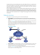
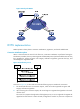
Network requirements
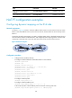
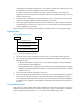
As shown in Figure 67, Router C with IPv6 address 2001::2/64 on an IPv6 network can communicate
with Router A with IPv4 address 8.0.0.2/24 on an IPv4 network.
To meet the preceding requirement, you need to configure Router B that is deployed between the IPv4
network and IPv6 network as a NAT-PT device, and configure static mappings on the IPv4 side and IPv6
side on Router B, so that Router A and Router C can communicate with each other.
Figure 67 Network diagram
Configuration procedure
1. Configure Router B:
# Configure interface addresses and enable NAT-PT on the interfaces.
<RouterB> system-view
[RouterB] ipv6
[RouterB] interface serial 2/0
[RouterB-Serial2/0] ip address 8.0.0.1 255.255.255.0