
R2511-HP MSR Router Series Layer 3 - IP Services Configuration Guide(V5)


207
Configuration example
Network requirements
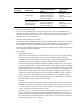
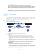
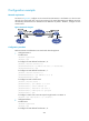
As shown in Figure 83, configure an IPv4 network between Router A and Router B so the two IPv6
networks can reach each other over the IPv4 network. The tunnel destination IPv4 address cannot be
automatically obtained from the destination IPv6 addresses of packets. Therefore, configure an IPv6
manual tunnel.
Figure 83 Network diagram
Configuration procedure
Make sure Router A and Router B can reach each other through IPv4.
• Configure Router A:
# Enable IPv6.
<RouterA> system-view
[RouterA] ipv6
# Configure an IPv4 address for Ethernet 1/2.
[RouterA] interface ethernet 1/2
[RouterA-Ethernet1/2] ip address 192.168.100.1 255.255.255.0
[RouterA-Ethernet1/2] quit
# Configure an IPv6 address for Ethernet 1/1.
[RouterA] interface ethernet 1/1
[RouterA-Ethernet1/1] ipv6 address 3002::1 64
[RouterA-Ethernet1/1] quit
# Configure an IPv6 manual tunnel.
[RouterA] interface tunnel 0
[RouterA-Tunnel0] ipv6 address 3001::1/64
[RouterA-Tunnel0] source ethernet 1/2
[RouterA-Tunnel0] destination 192.168.50.1
[RouterA-Tunnel0] tunnel-protocol ipv6-ipv4
[RouterA-Tunnel0] quit
# Configure a static route to IPv6 Group 2 through Tunnel 0 on Router A.
[RouterA] ipv6 route-static 3003:: 64 tunnel 0
• Configure Router B:
# Enable IPv6.
<RouterB> system-view
[RouterB] ipv6
# Configure an IPv4 address for Ethernet 1/2.