
R2511-HP MSR Router Series Layer 3 - IP Services Configuration Guide(V5)

13
Configuration procedure
# Configure the IP address of interface Ethernet 1/2.
<Router> system-view
[Router] interface ethernet 1/2
[Router-Ethernet1/2] ip address 192.168.10.99 255.255.255.0
# Enable proxy ARP on interface Ethernet 1/2.
[Router-Ethernet1/2] proxy-arp enable
[Router-Ethernet1/2] quit
# Configure the IP address of interface Ethernet 1/1.
[Router] interface ethernet 1/1
[Router-Ethernet1/1] ip address 192.168.20.99 255.255.255.0
# Enable proxy ARP on interface Ethernet 1/1.
[Router-Ethernet1/1] proxy-arp enable
[Router-Ethernet1/1] quit
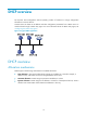
After completing preceding configurations, use the ping command to verify the connectivity between
Host A and Host D.
Local proxy ARP configuration example in case of port isolation
Network requirements
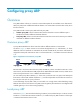
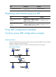
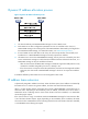
As shown in Figure 7, Host A and Host B belong to the same VLAN, and connect to the switch through
Ethernet 1/3 and Ethernet 1/1 respectively. The switch connects to the router through Ethernet 1/2.
Configure port isolation on Ethernet 1/3 and Ethernet 1/1 of the switch to isolate Host A from Host B at
Layer 2. Enable local proxy ARP on the router to allow communication between Host A and Host B at
Layer 3.
If the two ports (Ethernet 1/3 and Ethernet 1/1) on the switch are isolated only at Layer 2, you can
enable communication between the two hosts by configuring local proxy ARP on VLAN-interface 2 of the
switch.
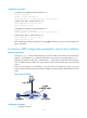
Figure 7 Network diagram
Configuration procedure
1. Configure the switch: