
R2511-HP MSR Router Series Layer 3 - IP Services Configuration Guide(V5)

252
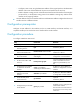
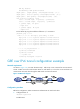
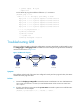
Figure 101 Network diagram
Configuration procedure
Before the configuration, make sure Router A and Router B can reach each other.
1. Configure Router A:
# Configure an IPv4 address for interface Ethernet 1/1.
<RouterA> system-view
[RouterA] interface ethernet 1/1
[RouterA-Ethernet1/1] ip address 10.1.1.1 255.255.255.0
[RouterA-Ethernet1/1] quit
# Configure an IPv4 address for interface Serial 2/0, the physical interface of the tunnel.
[RouterA] interface serial 2/0
[RouterA-Serial2/0] ip address 1.1.1.1 255.255.255.0
[RouterA-Serial2/0] quit
# Create a tunnel interface named Tunnel0.
[RouterA] interface tunnel 0
# Configure an IPv4 address for the tunnel interface Tunnel0.
[RouterA-Tunnel0] ip address 10.1.2.1 255.255.255.0
# Configure the tunnel encapsulation mode as GRE over IPv4.
[RouterA-Tunnel0] tunnel-protocol gre
# Configure the source address of the tunnel interface Tunnel0 as the IP address of Serial 2/0.
[RouterA-Tunnel0] source 1.1.1.1
# Configure the destination address of the tunnel interface Tunnel0 as the IP address of Serial 2/1
on Router B.
[RouterA-Tunnel0] destination 2.2.2.2
[RouterA-Tunnel0] quit
# Configure a static route from Router A through the tunnel interface Tunnel0 to Group 2.
[RouterA] ip route-static 10.1.3.0 255.255.255.0 tunnel 0
2. Configure Router B:
# Configure an IPv4 address for interface Ethernet 1/1.
<RouterB> system-view
[RouterB] interface ethernet 1/1
[RouterB-Ethernet1/1] ip address 10.1.3.1 255.255.255.0
[RouterB-Ethernet1/1] quit
# Configure an IPv4 address for interface Serial 2/1, the physical interface of the tunnel.
[RouterB] interface serial 2/1
[RouterB-Serial2/1] ip address 2.2.2.2 255.255.255.0
[RouterB-Serial2/1] quit
# Create a tunnel interface named Tunnel0.
[RouterB] interface tunnel 0