
R2511-HP MSR Router Series Layer 3 - IP Services Configuration Guide(V5)

257
10 packets output, 840 bytes
0 output error
# From Router B, ping the IP address of Ethernet 1/1 on Router A.
[RouterB] ping 10.1.1.1
PING 10.1.1.1: 56 data bytes, press CTRL_C to break
Reply from 10.1.1.1: bytes=56 Sequence=1 ttl=255 time=3 ms
Reply from 10.1.1.1: bytes=56 Sequence=2 ttl=255 time=2 ms
Reply from 10.1.1.1: bytes=56 Sequence=3 ttl=255 time=2 ms
Reply from 10.1.1.1: bytes=56 Sequence=4 ttl=255 time=2 ms
Reply from 10.1.1.1: bytes=56 Sequence=5 ttl=255 time=3 ms
--- 10.1.1.1 ping statistics ---
5 packet(s) transmitted
5 packet(s) received
0.00% packet loss
round-trip min/avg/max = 2/2/3 ms
Troubleshooting GRE
The key to configuring GRE is to keep the configurations consistent. Most faults can be located by using
the debugging gre or debugging tunnel command. This section analyzes one type of fault for illustration,
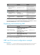
with the scenario shown in Figure 103.
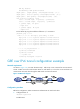
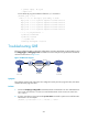
Figure 103 Network diagram
Symptom
The interfaces at both ends of the tunnel are configured correctly and can ping each other, but Host A
and Host B cannot ping each other.
Solution
1. Execute the display ip routing-table command on Router A and Router C to view whether Router A
has a route over tunnel 0 to 10.2.0.0/16 and whether Router C has a route over tunnel 0 to
10.1.0.0/16.
2. If such a route does not exist, execute the ip route-static command in system view to add the route.
Take Router A as an example:
[RouterA] ip route-static 10.2.0.0 255.255.0.0 tunnel 0
IP network
IP network
Router A
Router B
Router C
Host A
Host B
10.1.1.1/16 10.2.1.1/16
Tunnel0 Tunnel0
IP network
GRE Tunnel