
R2511-HP MSR Router Series Layer 3 - IP Services Configuration Guide(V5)


330
Bandwidth-based load sharing configuration
example
Network requirements
Router A in Figure 133 has the following three equal-cost routes to the destination network 10.2.1.0/24:
<RouterA> display fib 10.2.1.0
Destination count: 1 FIB entry count: 3
Flag:
U:Useable G:Gateway H:Host B:Blackhole D:Dynamic S:Static
R:Relay
Destination/Mask Nexthop Flag OutInterface InnerLabel Token
10.2.1.0/24 10.1.1.2 GSU Eth1/1 Null Invalid
10.1.2.2 GSU Atm1/0 Null Invalid
10.1.3.2 GSU Serial2/0 Null Invalid
Use the display load-sharing ip address command to display the bandwidths on interfaces.
<RouterA> display load-sharing ip address 10.2.1.0 24
There are/is totally 3 route entry(s) to the same destination network.
Nexthop Packet(s) Bandwidth[KB] Flow(s) Interface
10.1.1.2 763851 100000 0 Ethernet1/1
10.1.2.2 1193501 155000 0 Atm1/0
10.1.3.2 15914 2048 0 Serial2/0
At this time, the device performs load sharing over the interfaces based on their default bandwidths.
Configure bandwidths on ATM 1/0, Ethernet 1/1, and Serial 2/0 as 100 kbps, 200 kbps, and 300
kbps respectively for load sharing.
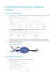
Figure 133 Network diagram
Configuration procedure
# On Router A, configure bandwidths for the three interfaces.
<RouterA> system-view
[RouterA] interface ethernet 1/1
[RouterA-Ethernet1/1] load-bandwidth 200
[RouterA-Ethernet1/1] quit
[RouterA] interface atm 1/0
[RouterA-Atm1/0] load-bandwidth 100
[RouterA-Atm1/0] quit