
R2511-HP MSR Router Series Layer 3 - IP Services Configuration Guide(V5)


42
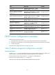
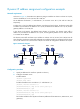
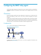
Figure 22 Network diagram
Configuration procedure
1. Configure the IP address of Ethernet 1/1 on Router A:
<RouterA> system-view
[RouterA] interface ethernet 1/1
[RouterA-Ethernet1/1] ip address 10.1.1.1 25
[RouterA-Ethernet1/1] quit
2. Configure the DHCP server:
# Enable DHCP.
[RouterA] dhcp enable
# Enable the DHCP server on Ethernet 1/1.
[RouterA] interface ethernet 1/1
[RouterA-Ethernet1/1] dhcp select server global-pool
[RouterA-Ethernet1/1] quit
# Create DHCP address pool 0, and configure a static binding, DNS server and gateway in it.
[RouterA] dhcp server ip-pool 0
[RouterA-dhcp-pool-0] static-bind ip-address 10.1.1.5.25
[RouterA-dhcp-pool-0] static-bind client-identifier
3030-3066-2e65-3230-302e-3030-3032-2d45-7468-6572-6e65-7430-2f30
[RouterA-dhcp-pool-0] dns-list 10.1.1.2
[RouterA-dhcp-pool-0] gateway-list 10.1.1.126
[RouterA-dhcp-pool-0] quit
# Create DHCP address pool 1, and configure a static binding, DNS server and gateway in it.
[RouterA] dhcp server ip-pool 1
[RouterA-dhcp-pool-1] static-bind ip-address 10.1.1.6.25
[RouterA-dhcp-pool-1] static-bind mac-address 000f-e200-01c0
[RouterA-dhcp-pool-1] dns-list 10.1.1.2
[RouterA-dhcp-pool-1] gateway-list 10.1.1.126
Verifying the configuration
After the preceding configuration is complete, Router B can obtain IP address 10.1.1.5 and other network
parameters, and Router C can obtain IP address 10.1.1.6 and other network parameters from Router A.
You can use the display dhcp server ip-in-use command on the DHCP server to view the IP addresses
assigned to the clients.
Router B
DHCP Client
DNS server
10.1.1.2/25
Router A
DHCP server
Eth1/1
10.1.1.1/25
Eth1/1
Gateway
10.1.1.126/25
Router C
BOOTP Client
Eth1/1