
R2511-HP MSR Router Series Layer 3 - IP Services Configuration Guide(V5)

61
DHCP client configuration example
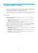
Network requirements
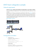
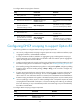
As shown in Figure 29, Router B contacts the DHCP server through Ethernet 1/1 to obtain an IP address,
DNS server address, and static route information. The DHCP client IP address resides on network
10.1.1.0/24. The DNS server address is 20.1.1.1. The next hop of the static route to network 20.1.1.0/24
is 10.1.1.2.
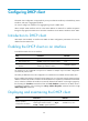
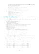
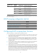
The DHCP server uses Option 121 to assign static route information to DHCP clients. Figure 28 sh
ows the
format of Option 121. The destination descriptor field comprises two parts, subnet mask length and
destination network address. In this example, the value of the destination descriptor field takes 18 14 01
01, a hexadecimal number indicating that the subnet mask length is 24 and destination network address
is 20.1.1.0, and the value of the next hop address field takes 0A 01 01 02, a hexadecimal number
indicating that the next hop is 10.1.1.2.
Figure 28 Option 121 format
Figure 29 Network diagram
Configuration procedure
1. Configure Router A:
# Specify the IP address of Ethernet 1/1.
<RouterA> system-view
[RouterA] interface ethernet 1/1
[RouterA-Ethernet1/1] ip address 10.1.1.1 24
[RouterA-Ethernet1/1] quit
# Enable DHCP.
[RouterA] dhcp enable
# Exclude an IP address from automatic allocation.
[RouterA] dhcp server forbidden-ip 10.1.1.2