HP MSR Router Series MPLS Configuration Guide(V5) Part number: 5998-2026 Software version: CMW520-R2511 Document version: 6PW103-20140128
Legal and notice information © Copyright 2014 Hewlett-Packard Development Company, L.P. No part of this documentation may be reproduced or transmitted in any form or by any means without prior written consent of Hewlett-Packard Development Company, L.P. The information contained herein is subject to change without notice.
Contents Configuring basic MPLS ·············································································································································· 1 Overview············································································································································································ 1 Basic concepts ·········································································································································
Basic concepts ······················································································································································· 36 MPLS L2VPN network models ······························································································································ 37 Remote connection establishment ························································································································ 37 Local connection establishment
MPLS L3VPN networking schemes ····················································································································· 109 MPLS L3VPN routing information advertisement ······························································································ 112 Inter-AS VPN ························································································································································ 113 Carrier's carrier ····························
Configuring BGP AS number substitution and SoO ························································································ 249 Configuring IPv6 MPLS L3VPN ······························································································································ 253 Overview······································································································································································· 253 IPv6 MPLS L3VPN packet forwardin
Configuring RSVP-TE advanced features ··················································································································· 339 Configuring RSVP reservation style ··················································································································· 339 Configuring RSVP state timers ···························································································································· 340 Configuring the RSVP refresh mechanism ·
Configuring L2VPN access to L3VPN or IP backbone ························································································· 423 Overview······································································································································································· 423 Conventional L2VPN access to L3VPN or IP backbone ·················································································· 423 Improved L2VPN access to L3VPN or IP backbone·······
Configuring basic MPLS Overview Multiprotocol Label Switching (MPLS) enables connection-oriented label switching on connectionless IP networks. It integrates both the flexibility of IP routing and the level of simplicity of Layer 2 switching. MPLS has the following advantages: • MPLS forwards packets according to short- and fixed-length labels, instead of Layer 3 header analysis and complicated routing table lookup, enabling highly-efficient and fast data forwarding on backbone networks.
• S—One bit in length. MPLS supports multiple levels of labels. This field indicates whether a label is at the bottom of the label stack. A value of 1 indicates that the label is at the bottom of the label stack. • TTL—Eight bits in length. Like the homonymous IP header field, it is used to prevent loops. LSR A label switching router (LSR) is a fundamental component on an MPLS network. LSRs support label distribution and label swapping.
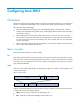
MPLS network structure Figure 3 MPLS network structure LSRs in the same routing or administrative domain form an MPLS domain. An MPLS domain has the following LSR types: • Ingress LSRs—Receive and label packets coming into the MPLS domain. • Transit LSRs—Forward packets along LSPs to their egress LERs according to the labels. • Egress LSRs—Remove labels from packets and forward the packets to their destination networks.
A dynamic LSP is established in the following procedure: A downstream LSR classifies FECs according to destination addresses. It assigns a label to a FEC, and distributes the FEC-label binding to its upstream LSR, which then establishes an LFIB entry for the FEC according to the binding information. After all LSRs along the packet forwarding path establish a LFIB entry for the FEC, an LSP is established for packets of this FEC.
• In DU mode, an LSR assigns a label to a FEC and then distributes the FEC-label binding to its upstream LSR without solicitation. The device supports only the DU mode. • In DoD mode, an LSR assigns a label to a FEC and distributes the FEC-label binding to its upstream LSR only when it receives a label request from the upstream LSR. To establish an LSP, an upstream LSR and its downstream LSR must use the same label advertisement mode.
MPLS forwarding LFIB An LFIB includes the following table entries: • Next Hop Label Forwarding Entry—NHLFE describes the label operation to be performed. It is used to forward MPLS packets. • FEC to NHLFE map—FTN maps each FEC to a set of NHLFEs at the ingress LSR. The FTN map is used for forwarding unlabeled packets that need MPLS forwarding. When an LSR receives an unlabeled packet, it looks for the corresponding FIB entry.
containing the Token value. According to the NHLFE entry, Router C swaps the original label with label 50, and then forwards the labeled packet to the next hop LSR (Router D) through the outgoing interface (Ethernet 1/2). 3. Upon receiving the labeled packet, Router D (the egress) looks for the ILM entry according to the label (50) to get the Token value. Because the Token is empty, Router D removes the label from the packet.
LDP operation LDP goes through the following phases in operation: 1. Discovery: Each LSR sends hello messages periodically to notify neighboring LSRs of its presence. In this way, LSRs can automatically discover their LDP peers. LDP provides the following discovery mechanisms: { { Basic discovery mechanism—Discovers directly connected LSRs and establishes link hello adjacencies with them. An LSR periodically sends LDP link Hello messages to multicast address 224.0.0.
An LSR determines the integrity of an LDP session according to the LDP PDU (which carries one or more LDP messages) transmitted on the session. Before the Keepalive timer times out, if two LDP peers have no information to exchange, they can send Keepalive messages to each other to maintain the LDP session. If an LSR does not receive any LDP PDU from its peer during a Keepalive interval, it closes the TCP connection and terminates the LDP session. { Receiving a shutdown message from the peer.
Task Remarks Sending back ICMP TTL exceeded messages for MPLS TTL expired packets Optional. Configuring LDP GR Optional. Setting MPLS statistics interval Inspecting LSPs Optional. Configuring MPLS LSP ping Optional. Configuring MPLS LSP tracert Optional. Enabling MPLS trap Optional. Enabling the MPLS function In an MPLS domain, you must enable MPLS on all routers before you can configure other MPLS features.
Configuration prerequisites Before you configure a static LSP, complete the following tasks: • Determine the ingress LSR, transit LSRs, and egress LSR for the static LSP. • Enable MPLS on all these LSRs. • Make sure the ingress LSR has a route to the FEC destination. This is not required on the transit LSRs and egress LSR.
Configuring MPLS LDP capability Step Command Remarks 1. Enter system view. system-view N/A 2. Enable LDP capability globally and enter MPLS LDP view. mpls ldp Not enabled by default. Optional. By default, the LDP LSR ID is the same as the MPLS LSR ID. You must perform this task only in a multi-VPN context to make sure that different LDP instances have different LDP LSR IDs if their address spaces overlap. Otherwise, TCP connections cannot be established. 3. Configure the LDP LSR ID.
Step Command Remarks Optional. Configure the LDP transport address. 5. mpls ldp transport-address { ip-address | interface } The default takes the value of the MPLS LSR ID. The specified IP address must be the IP address of an interface on the device. Configuring remote LDP session parameters LDP sessions established between remote LDP peers are remote LDP sessions. Remote LDP sessions are mainly used in Martini MPLS L2VPN and MPLS LDP over MPLS TE.
Step Command Remarks Optional. Configure the LDP transport address. 7. mpls ldp transport-address ip-address The default takes the value of the MPLS LSR ID. The specified IP address must be the IP address of an interface on the device. Configuring PHP When specifying the type of label for an egress to distribute to a penultimate hop, check whether the penultimate hop supports PHP.
Step Command Remarks Optional. By default, only host routes with 32-bit masks can trigger establishment of LSPs. 3. Configure the LSP establishment triggering policy. lsp-trigger [ vpn-instance vpn-instance-name ] { all | ip-prefix prefix-name } If the vpn-instance vpn-instance-name option is specified, the command configures an LSP establishment triggering policy for the specified VPN. Otherwise, the command configures an LSP establishment triggering policy for the public network routes.
Configuring LDP loop detection LSPs established in an MPLS domain might be looping. The LDP loop detection mechanism can detect looping LSPs and prevent LDP messages from looping forever. LDP loop detection can be in either of the following modes: Maximum hop count • A label request message or label mapping message carries information about its hop count, which increments by 1 for each hop.
Configuring LDP MD5 authentication LDP sessions are established based on TCP connections. To improve the security of LDP sessions, you can configure MD5 authentication for the underlying TCP connections, so that the TCP connections can be established only if the peers have the same authentication password. IMPORTANT: To establish an LDP session successfully between two LDP peers, make sure their LDP MD5 authentication settings are the same. To configure LDP MD5 authentication: Step Command Remarks 1.
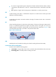
Label advertisement control Label advertisement control is for filtering label bindings to be advertised. A downstream LSR advertises only the label bindings of the specified FECs to the specified upstream LSR. As shown in Figure 9, downstream device LSR A advertises to upstream device LSR B only label bindings with FEC destinations permitted by prefix list B, and advertises to upstream device LSR C only label bindings with FEC destinations permitted by prefix list C.
To configure a DSCP value for outgoing LDP packets: Step Command Remarks 1. Enter system view. system-view N/A 2. Enter MPLS LDP view. mpls ldp N/A 3. Configure a DSCP value for outgoing LDP packets. dscp dscp-value By default, the DSCP value for outgoing LDP packets is 48. Maintaining LDP sessions This section describes how to detect communication failures between remote LDP peers and reset LDP sessions.
Configuring MPLS fast forwarding MPLS fast forwarding is designed to improve MPLS forwarding efficiency. With the idea of "route once, switch many," MPLS fast forwarding forwards the first packet of a data stream based on the normal MPLS forwarding process and, during this period, creates a fast forwarding entry to record the label stack and the link layer header of the packet.
• An interface always forwards MPLS packets carrying L2VPN packets, even if the MPLS packet size exceeds the interface MPLS MTU. However, whether the forwarding succeeds depends on the actual forwarding capacity of the interface. • An interface drops MPLS packets carrying IPv6 packets if the MPLS packet size exceeds the interface MPLS MTU. At the same time, the device sends the interface MPLS MTU to the sender in a "Packet Too Big" ICMPv6 message.
Figure 11 TTL processing when TTL propagation is disabled Configuration guidelines HP recommends configuring the same TTL processing mode on all LSRs along an LSP. To enable IP TTL propagation for a VPN, you must enable it on all PE devices in the VPN, so that you can get the same traceroute result (hop count) from those PEs. For more information about PEs, see "Configuring MPLS L3VPN." Configuration procedure To configure TTL propagation of MPLS: Step Command Remarks 1. Enter system view.
To configure the device to send back an ICMP TTL exceeded message for a received MPLS TTL expired packet: Step Command Remarks 1. Enter system view. system-view N/A 2. Enter MPLS view. mpls N/A 3. Enable the device to send back an ICMP TTL exceeded message when it receives an MPLS TTL expired packet. ttl expiration enable Optional. Enabled by default. Optional. 4.
Figure 12 LDP GR GR helper GR restarter GR helper GR helper LDP session with GR capability Two LDP peers perform GR negotiation when establishing an LDP session. The LDP session established is GR capable only when both peers support LDP GR. LDP GR works in the following procedure: 1. Whenever restarting, the GR restarter preserves all MPLS forwarding entries, marks them as stale, and starts the MPLS forwarding state holding timer for them. 2.
Step Command Remarks 1. Enter system view. system-view N/A 2. Enter MPLS LDP view. mpls ldp N/A 3. Enable MPLS LDP GR. graceful-restart Disabled by default. 4. Set the FT reconnect time. graceful-restart timer reconnect timer Optional. 5. Set the LDP neighbor liveness time. graceful-restart timer neighbor-liveness timer Optional. Set the LDP recovery time. graceful-restart timer recovery timer Optional. 6. 300 seconds by default. 120 seconds by default. 300 seconds by default.
Configuring MPLS LSP ping MPLS LSP ping is for testing the connectivity of an LSP. At the ingress, it adds the label for the FEC to be inspected into an MPLS echo request, which then is forwarded along the LSP to the egress. The egress processes the request packet and returns an MPLS echo reply to the ingress. An MPLS echo reply carrying a success notification indicates that the LSP is normal, and an MPLS echo reply carrying an error code indicates that the LSP has failed.
Displaying and maintaining MPLS Displaying MPLS operation Task Command Remarks Display information about one or all interfaces with MPLS enabled. display mpls interface [ interface-type interface-number ] [ verbose ] [ | { begin | exclude | include } regular-expression ] Available in any view. Display information about ILM entries. display mpls ilm [ label ] [ verbose ] [ | { begin | exclude | include } regular-expression ] Available in any view.
Task Command Remarks Display information about MPLS fast forwarding entries. display mpls fast-forwarding cache [ verbose ] [ | { begin | exclude | include } regular-expression ] Available in any view. Displaying MPLS LDP operation Task Command Remarks Display information about LDP. display mpls ldp [ all [ verbose ] [ | { begin | exclude | include } regular-expression ] ] Available in any view. Display label advertisement information for the specified FEC.
Clearing MPLS statistics Task Command Remarks Clear MPLS statistics for one or all MPLS interfaces. reset mpls statistics interface { interface-type interface-number | all } Available in user view. Clear MPLS statistics for all LSPs or the LSP with a specific index or name. reset mpls statistics lsp { index | all | name lsp-name } Available in user view. Clear information in the MPLS fast forwarding cache. reset mpls fast-forwarding cache Available in user view.
[RouterA] ip route-static 21.1.1.0 24 10.1.1.2 # Configure a static route to network 11.1.1.0/24 on Router C. system-view [RouterC] ip route-static 11.1.1.0 255.255.255.0 20.1.1.1 3. Enable MPLS: # Configure MPLS on Router A. [RouterA] mpls lsr-id 1.1.1.9 [RouterA] mpls [RouterA-mpls] quit [RouterA] interface serial 2/0 [RouterA-Serial2/0] mpls [RouterA-Serial2/0] quit # Configure MPLS on Router B. [RouterB] mpls lsr-id 2.2.2.
[RouterA] static-lsp egress CtoA incoming-interface serial 2/0 in-label 70 Verifying the configuration # Execute the display mpls static-lsp command on each router to display static LSP information. This example uses Router A. [RouterA] display mpls static-lsp total statics-lsp : 2 Name FEC AtoC 21.1.1.0/24 CtoA -/- I/O Label NULL/30 70/NULL I/O If -/S2/0 S2/0/- State Up Up # On Router A, test the connectivity of the LSP from Router A to Router C. [RouterA] ping lsp -a 11.1.1.1 ipv4 21.1.1.
Figure 14 Network diagram Configuration considerations Enable LDP on the LSRs. LDP dynamically distributes labels and establishes LSPs and thus there is no need to manually configure labels for LSPs. LDP uses routing information for label distribution. You must configure a routing protocol to learn routing information. OSPF is used in this example. Configuration procedure 1. Configure IP addresses for the interfaces, according to Figure 14. (Details not shown.) 2.
[RouterC-ospf-1] quit # Verify that each router has learned the routes to other routers. This example uses Router A. [RouterA] display ip routing-table Routing Tables: Public Destinations : 11 3. Destination/Mask Proto 1.1.1.9/32 Routes : 11 Pre Cost NextHop Interface Direct 0 0 127.0.0.1 InLoop0 2.2.2.9/32 OSPF 10 1 10.1.1.2 S2/0 3.3.3.9/32 OSPF 10 2 10.1.1.2 S2/0 10.1.1.0/24 Direct 0 0 10.1.1.1 S2/0 10.1.1.1/32 Direct 0 0 127.0.0.1 InLoop0 11.1.1.0/24 Direct 0 0 11.
[RouterC-mpls] quit [RouterC] mpls ldp [RouterC-mpls-ldp] quit [RouterC] interface serial 2/0 [RouterC-Serial2/0] mpls [RouterC-Serial2/0] mpls ldp [RouterC-Serial2/0] quit Two local LDP sessions are established, one between Router A and Router B and the other between Router B and Router C. # Execute the display mpls ldp session command on each router to display the LDP session information, and execute the display mpls ldp peer command to display the LDP peer information. This example uses Router A.
------------------------------------------------------------------SN DestAddress/Mask In/OutLabel Next-Hop In/Out-Interface -----------------------------------------------------------------1 1.1.1.9/32 3/NULL 127.0.0.1 -------/InLoop0 2 2.2.2.9/32 NULL/3 10.1.1.2 -------/S2/0 3 3.3.3.9/32 NULL/1024 10.1.1.2 -------/S2/0 4 11.1.1.0/24 3/NULL 0.0.0.0 -------/Eth1/1 5 20.1.1.0/24 NULL/3 10.1.1.2 -------/S2/0 6 21.1.1.0/24 NULL/1027 10.1.1.
Configuring MPLS L2VPN MPLS L2VPN can provide both point-to-point connections and point-to-multipoint connections. This chapter describes only the MPLS L2VPN technologies that provide point-to-point connections. Overview MPLS L2VPN is an MPLS-based Layer 2 VPN technology. It uses MPLS to establish Layer 2 connections between network nodes.
MPLS L2VPN network models MPLS L2VPN network models include remote connection model and local connection model. Remote connection model As shown in Figure 15, this model connects two Layer 2 customer networks over an MPLS or IP backbone. Figure 15 Remote connection Local connection model As shown in Figure 16, this model connects two Layer 2 customer networks to the same PE. The customer networks exchange packets with each other through the PE. The PE functions like a Layer 2 switch.
3. Set up ACs and bind the ACs to the VC, so the PEs can forward user packets from ACs through the VC: a. Set up an AC: Configure the link layer protocol on a PE and the connected CE to set up a link layer connection (such as a PPP connection) between the PE and the CE. b. Bind the AC to the VC: For most link layer protocols, you bind the AC to the VC by binding the PE's Layer 3 interface connected to the CE to the VC.
1. Set up ACs: Configure the link layer protocol on the PE and a connected CE to set up a link layer connection (such as a PPP connection) between the PE and the CE. 2. Bind the two ACs that connect the two CEs: You can bind the ACs by binding the PE's Layer 3 interfaces connected to the two CEs. After the binding, the PE forward packets received from one AC to another. As shown in Figure 18, MPLS L2VPN forwards Layer 2 packets received from CE 1 directly to CE 2.
2. After the P device receives the packet, it looks up the label forwarding table, and swaps label 300 with label 310. 3. After receiving the packet, PE 2 deletes the label from the packet, and then forwards the packet out of the bound interface Interface B to CE 2. Unlike other MPLS L2VPN modes, CCC employs only one level of label to transfer user packets. A static LSP forwards only packets from the AC bound to the static LSP. Therefore, CCC uses LSPs exclusively.
• Route distinguisher—To distinguish CEs with the same CE ID in different VPNs, Kompella adds an RD before a CE ID. An RD and a CE ID uniquely identify a CE. • Route target—Kompella uses the BGP route target attribute (also called "VPN target" attribute) to identify VPNs to make sure CEs in the same VPN can establish a connection and CEs in different VPNs cannot.
Figure 21 VC label calculation CE 2 Label block 1: 1000/0/5 Label block 2: 1055/5/10 Label block for CE 2: 2000/0/15 Label block for CE 12: 3000/0/15 P Label block allocated Label block allocated PE 1 VPN 1 CE 1 VPN 1 PE 2 VC labels calculated VC connected CE 1 and CE 2: local VC label: 1002 remote VC label: 2001 VC connected CE 1 and CE 12: local VC label: 1062 remote VC label: 3001 VC connected CE 1 and CE 2: local VC label: 2001 remote VC label: 1002 VC connected CE 1 and CE 12: local VC label:
As shown in Figure 22, CE 1 and CE 2 belong to VPN 1. CE 3 and CE 4 belong to VPN 2. Configure route targets for the two VPNs to make sure CEs in the same VPN can set up a VC and CEs in different VPNs cannot. A VC is set up as follows (take the VC between CE 1 and CE 2 as an example): 1. PE 1 sends the RD, CE ID, route target (export target configured for VPN 1 on PE 1), and the label block for CE 1 to PE 2 in a BGP update message. 2.
Mode VC label encapsulation and distribution Advantages and disadvantages Application scenario Advantages: • On a carrier network, only PEs need to save a Martini VC label encapsulation: two levels of labels VC label distribution: LDP few VC label to LSP mappings. The P devices do not need to save any Layer 2 VPN information. • To add a new VC, you only need to configure the PEs of the VC, without interrupting network operation. Sparse Layer 2 connections, such as a star topology.
1. After receiving a packet from an interface, the PE searches for the VC bound to the interface. 2. The PE encapsulates the packet and sends the packet to the peer PE through the VC. 3. The peer PE removes the outer encapsulation to get the original PPP or HDLC packet, and then forwards the packet to the user network.
For more information about ATM, see Layer 2—WAN Configuration Guide. Figure 23 ATM AAL5 transparent transport Control word The control word field is between the VC label and the Layer 2 data. It carries information about the Layer 2 packet, such as the sequence number. The control word filed has the following functions: • Avoid packet disorder—In case of multi-path forwarding, packets received might be disordered.
Figure 24 VC redundancy protection in an MPLS L2VPN The MPLS L2VPN determines whether the primary VC fails according to the LDP session status and the BFD result. The backup VC is used in the following circumstances: • The tunnel of the primary VC is deleted or no longer meets the tunneling policy, causing the primary VC to go down. • The BFD protocol detects that the primary VC has failed.
As shown in Figure 25, CE 1 is connected to PE 1 through an Ethernet link and CE 2 is connected to PE 2 through a PPP link. The VC setup mode is Martini. In such a scenario, a packet is forwarded in the following procedure: 1. CE 1 sends an Ethernet frame destined for CE 2 to PE 1. 2. PE 1 checks whether the packet encapsulated in the received Ethernet frame is an IP packet.
{ • Configure the PE as the FR DCE and the CE as the DTE, so that the PE can inform the CE of DLCI changes. When a CE connects to PE through an ATM AAL5 link: { { { On the PE, configure the interworking feature on an ATM point-to-point sub-interface. Only an ATM point-to-point sub-interface supports the interworking feature.
Configuring basic MPLS L2VPN Step Command Remarks 1. Enter system view. system-view N/A 2. Configure the LSR ID. mpls lsr-id lsr-id N/A 3. Configure basic MPLS and enter MPLS view. mpls N/A 4. Return to system view. quit N/A 5. Enable L2VPN and enter L2VPN view. l2vpn Disabled by default. 6. Enable MPLS L2VPN. mpls l2vpn Disabled by default. Configuring a PE-CE interface A PE-CE interface refers to a PE's interface connected to a CE.
Configuring FR DLCI or FR port mode encapsulation Step 1. Enter system view. Command Remarks system-view N/A 2. Enter interface view. interface { serial | pos } interface-number After you configure FR DLCI or FR port mode encapsulation on a serial interface, you must use the reset fr inarp command to clear FR dynamic address mappings between the PE and the CE. For more information about the reset fr inarp command, see Layer 2—WAN Command Reference. 3. Configure the link layer protocol.
Configuring VLAN encapsulation Step Command Remarks 1. Enter system view. system-view N/A 2. Enter interface view. interface interface-type { interface-number | interface-number.subnumber } N/A 3. Specify the IP address or MAC address of the default next hop. Required to support MPLS L2VPN interworking. default-nexthop { ip ip-address | mac { mac-address | broadcast } } By default, the default next hop information is not specified. This command is not available for VLAN interfaces.
Configuring a remote CCC connection To configure a remote CCC connection, perform the following configurations on the PE and P devices: • On the two PEs of the connection, use the ccc interface in-label out-label command to specify the incoming and the outgoing labels, and other information as needed. You do not need to configure two static LSPs (with the static-lsp command) for each remote CCC connection.
Configure a primary static VC and a backup static VC on a Layer 3 interface. This method implements VC redundancy. • Configuring a static VC on a Layer 3 interface Step Command Remarks 1. Enter system view. system-view N/A 2. Enter the view of the interface connecting the CE. interface interface-type interface-number N/A Create a static VC.
on each PE to establish a remote session between the two PEs and transfer VC FECs and VC labels through the session. 2. Create a Martini VC on a Layer 3 interface. In this way, packets arriving at this interface are forwarded over the created VC. If the Layer 3 interface is a VLAN interface, all packets carrying the tag of the VLAN are forwarded over the VC, no matter which Layer 2 Ethernet interfaces that the packets arrive at.
Inspecting VCs On a MPLS L2VPN network, you can use the MPLS LSP ping function to test the VC connectivity and get necessary information for troubleshooting VC failures. On the local PE, the MPLS LSP ping function adds the label of the VC to be tested into MPLS Echo Request messages so the messages will travel along the VC. The local PE determines whether the VC is valid and reachable according to the replies received from the peer PE.
Creating and configuring an MPLS L2VPN Step 1. 2. 3. 4. Command Remarks Enter system view. system-view N/A Create an MPLS L2VPN and enter MPLS L2VPN view. mpls l2vpn vpn-name [ encapsulation { atm-aal5 | ethernet | fr | hdlc | ppp | vlan } [ control-word | no-control-word ] ] You must create an L2VPN on the PE for each VPN where a directly connected CE resides. When creating an L2VPN, you must specify an encapsulation type matching that of the AC link. Configure an RD for the MPLS L2VPN.
The subsequent label blocks are calculated in the same way. For example, if you execute the following commands on the PE in order, the PE assigns three label blocks. They are LB1/0/10, LB2/10/12, and LB3/22/14, where LB1, LB2, and LB3 are label values automatically selected by the PE. ce ce1 id 1 range 10 default-offset 0 ce ce1 id 1 range 22 ce ce1 id 1 range 36 ce-offset ce-id: Specifies the ID of the peer CE that establishes a local or remote connection with the local CE.
Step Command Create a Kompella connection. 4. connection [ ce-offset ce-id ] interface interface-type interface-number [ tunnel-policy tunnel-policy-name ] Remarks The ce-offset ce-id option determines whether the connection is a local connection or a remote connection. If the specified CE is connected to the same PE as the local CE, the connection is a local connection. Otherwise, the connection is a remote connection.
Configuring L2PT Layer 2 protocol tunneling (L2PT) allows CDP, GVRP, LACP, LLDP, PAGP, PVST, STP, UDLD, or VTP packets to traverse an MPLS L2VPN connection. It has the following operating modes: Tunnel mode—The PE replaces the protocol destination MAC address of packets from the private network with the L2PT multicast MAC address. If the destination MAC address of packets from the public network is the L2PT multicast MAC address, the PE replaces the MAC address with the protocol destination MAC address.
Task Command Remarks Display information about static VCs. display mpls static-l2vc [ interface interface-type interface-number [ service-instance instance-id ] ] [ | { begin | exclude | include } regular-expression ] Available in any view. Display information about Martini VCs. display mpls l2vc [ interface interface-type interface-number [ service-instance instance-id ] | remote-info ] [ | { begin | exclude | include } regular-expression ] Available in any view.
Figure 26 Network diagram Configuration considerations Because a local CCC connection is bidirectional, one local CCC connection is enough for CE 1 and CE 2 to communicate with each other. Configuration procedure 1. On CE 1, configure the link protocol type as PPP on Serial 2/0 (the interface connected to the PE), and configure an IP address for the interface. system-view [Sysname] sysname CE1 [CE1] interface serial 2/0 [CE1-Serial2/0] link-protocol ppp [CE1-Serial2/0] ip address 100.1.1.
[PE] interface serial 2/1 [PE-Serial2/1] link-protocol ppp [PE-Serial2/1] quit # Create a local connection between CE 1 and CE 2. [PE] ccc ce1-ce2 interface serial 2/0 out-interface serial 2/1 3. On CE 2, configure the link protocol type of Serial 2/0 (the interface connected to the PE) as PPP, and configure an IP address for the interface. system-view [Sysname] sysname CE2 [CE2] interface serial 2/0 [CE2-Serial2/0] link-protocol ppp [CE2-Serial2/0] ip address 100.1.1.
Figure 27 Network diagram Configuration considerations Because a local CCC connection is bidirectional, one local CCC connection is enough for CE 1 and CE 2 to communicate with each other. Because the PE-CE 1 link type is FR, and the PE-CE 2 link type is ATM, you must configure the local CCC connection on the PE to support IP interworking. Configuration procedure 1. Configure CE 1: # Configure the link protocol as frame relay on Serial 2/0, the interface connected to the PE.
# Enable L2VPN and MPLS L2VPN. [PE] l2vpn [PE-l2vpn] mpls l2vpn [PE-l2vpn] quit # Configure serial 2/0. [PE] interface serial 2/0 [PE-Serial2/0] link-protocol fr [PE-Serial2/0] fr interface-type dce [PE-Serial2/0] quit [PE] interface serial 2/0.1 p2p [PE-Serial2/0.1] fr dlci 100 [PE-fr-dlci-Serial2/0.1-100] quit [PE-Serial2/0.1] quit # Configure ATM 5/0. [PE] interface atm 5/0.1 p2p [PE-Atm5/0.1] pvc 100/200 [PE-atm-pvc-Atm5/0.1-100/200] map ip default [PE-atm-pvc-Atm5/0.1-100/200] quit [PE-Atm5/0.
Reply from 100.1.1.2: bytes=56 Sequence=1 ttl=255 time=2 ms Reply from 100.1.1.2: bytes=56 Sequence=2 ttl=255 time=3 ms Reply from 100.1.1.2: bytes=56 Sequence=3 ttl=255 time=3 ms Reply from 100.1.1.2: bytes=56 Sequence=4 ttl=255 time=2 ms Reply from 100.1.1.2: bytes=56 Sequence=5 ttl=255 time=3 ms --- 100.1.1.2 ping statistics --5 packet(s) transmitted 5 packet(s) received 0.
system-view [Sysname] sysname CE1 [CE1] interface pos 5/0 [CE1-POS5/0] link-protocol ppp [CE1-POS5/0] ip address 100.1.1.1 24 2. Configure PE 1: # Configure the LSR ID and enable MPLS globally. system-view [Sysname] sysname PE1 [PE1] interface loopback 0 [PE1-LoopBack0] ip address 10.0.0.1 32 [PE1-LoopBack0] quit [PE1] mpls lsr-id 10.0.0.1 [PE1] mpls [PE1-mpls] quit # Enable L2VPN and MPLS L2VPN. [PE1] l2vpn [PE1-l2vpn] mpls l2vpn [PE1-l2vpn] quit # Configure POS 5/0.
[P-POS5/1] mpls [P-POS5/1] quit # Configure POS 5/0, and enable MPLS. [P] interface pos 5/0 [P-POS5/0] link-protocol ppp [P-POS5/0] ip address 10.2.2.2 24 [P-POS5/0] mpls [P-POS5/0] quit # Create a static LSP for forwarding packets from PE 1 to PE 2. [P] static-lsp transit pe1_pe2 incoming-interface pos 5/1 in-label 200 outgoing-interface pos 5/0 out-label 201 # Create a static LSP for forwarding packets from PE 2 to PE 1.
[CE2-POS5/0] link-protocol ppp [CE2-POS5/0] ip address 100.1.1.2 24 Verifying the configuration # Verify that a remote CCC connection has been established on PE 1. [PE1] display ccc Total ccc vc : 1 Local ccc vc : 0, 0 up Remote ccc vc : 1, 1 up ***Name : ce1-ce2 Type : remote State : up Intf : POS5/0 (up) In-label : 100 Out-label : 200 Out-interface : POS5/1 # Verify that CE 1 and CE 2 can ping each other. [CE1] ping 100.1.1.2 PING 100.1.1.
Figure 29 Network diagram PE 1 P PE 2 Loop0 Loop0 Loop0 POS5/0 POS5/1 POS5/1 POS5/0 POS5/0 POS5/1 SVC POS5/0 POS5/0 CE 2 CE 1 Device Interface IP address Device Interface IP address CE 1 POS5/0 100.1.1.1/24 CE 2 POS5/0 100.1.1.2/24 PE 1 Loop0 192.2.2.2/32 P Loop0 192.4.4.4/32 POS5/1 10.1.1.1/24 POS5/0 10.2.2.2/24 Loop0 192.3.3.3/32 POS5/1 10.1.1.2/24 POS5/0 10.2.2.1/24 PE 2 Configuration considerations The following steps are required: 1.
# Enable L2VPN and MPLS L2VPN. [PE1] l2vpn [PE1-l2vpn] mpls l2vpn [PE1-l2vpn] quit # Enable LDP globally. [PE1] mpls ldp [PE1-mpls-ldp] quit # Configure the interface for connecting to the P device, and enable LDP on the interface. [PE1] interface pos 5/1 [PE1-POS5/1] link-protocol ppp [PE1-POS5/1] ip address 10.1.1.1 24 [PE1-POS5/1] mpls [PE1-POS5/1] mpls ldp [PE1-POS5/1] quit # Configure OSPF on PE 1 for establishing LSPs. [PE1] ospf [PE1-ospf-1] area 0 [PE1-ospf-1-area-0.0.0.0] network 10.1.1.1 0.0.0.
# Configure the interface connected with PE 2, and enable LDP on the interface. [P] interface pos 5/0 [P-POS5/0] link-protocol ppp [P-POS5/0] ip address 10.2.2.2 24 [P-POS5/0] mpls [P-POS5/0] mpls ldp [P-POS5/0] quit # Configure OSPF on the P router for establishing LSPs. [P] ospf [P-ospf-1] area 0 [P-ospf-1-area-0.0.0.0] network 10.1.1.2 0.0.0.255 [P-ospf-1-area-0.0.0.0] network 10.2.2.2 0.0.0.255 [P-ospf-1-area-0.0.0.0] network 192.4.4.4 0.0.0.0 [P-ospf-1-area-0.0.0.0] quit [P-ospf-1] quit 4.
[PE2] interface pos 5/1 [PE2-POS5/1] link-protocol ppp [PE2-POS5/1] mpls static-l2vc destination 192.2.2.2 transmit-vpn-label 200 receive-vpn-label 100 [PE2-POS5/1] quit 5. Configure CE 2: # Configure the link protocol as PPP on interface POS 5/0 (the interface connected to PE 2), and configure an IP address for the interface. system-view [Sysname] sysname CE2 [CE2] interface pos 5/0 [CE2-POS5/0] link-protocol ppp [CE2-POS5/0] ip address 100.1.1.
Figure 30 Network diagram Device Interface IP address Device Interface IP address CE 1 S2/0 100.1.1.1/24 CE 2 S2/0 100.1.1.2/24 PE 1 Loop0 192.2.2.2/32 P Loop0 192.4.4.4/32 S2/1 10.1.1.1/24 S2/0 10.1.1.2/24 PE 2 Loop0 192.3.3.3/32 S2/1 10.2.2.2/24 S2/1 10.2.2.1/24 Configuration procedure 1. On CE 1, configure the link protocol type as PPP on Serial 2/0 (the interface connected to the PE 1), and configure an IP address for the interface.
# Configure the peer relationship with PE 2 so that the LDP remote session can be established between them. [PE1] mpls ldp remote-peer 1 [PE1-mpls-ldp-remote-1] remote-ip 192.3.3.3 [PE1-mpls-ldp-remote-1] quit # Configure the interface connected to the P device, and enable LDP on the interface. [PE1] interface serial 2/1 [PE1-Serial2/1] link-protocol ppp [PE1-Serial2/1] ip address 10.1.1.1 24 [PE1-Serial2/1] mpls [PE1-Serial2/1] mpls ldp [PE1-Serial2/1] quit # Configure OSPF on PE 1 for establishing LSPs.
[P-Serial2/1] mpls [P-Serial2/1] mpls ldp [P-Serial2/1] quit # Configure OSPF on the P device for establishing LSPs. [P] ospf [P-ospf-1] area 0 [P-ospf-1-area-0.0.0.0] network 10.1.1.2 0.0.0.255 [P-ospf-1-area-0.0.0.0] network 10.2.2.2 0.0.0.255 [P-ospf-1-area-0.0.0.0] network 192.4.4.4 0.0.0.0 [P-ospf-1-area-0.0.0.0] quit [P-ospf-1] quit 4. Configure PE 2: # Configure the LSR ID and enable MPLS globally.
# Create a Martini VC on the interface connected to CE 2. The interface requires no IP address. [PE2] interface serial 2/0 [PE2-Serial2/0] mpls l2vc 192.2.2.2 101 [PE2-Serial2/0] quit On CE 2, configure the link protocol type as PPP on interface Serial 2/0 (the interface connected to the PE 1), and configure an IP address for the interface. 5. system-view [Sysname] sysname CE2 [CE2] interface serial 2/0 [CE2-Serial2/0] link-protocol ppp [CE2-Serial2/0] ip address 100.1.1.
CE 1 and CE 2 communicate through the primary VC when this VC is operating correctly. When PE 1 detects that the primary VC fails, it brings up the backup VC so that CE 1 and CE 2 can communicate through the backup VC. Figure 31 Network diagram Loop0 S2/0 S2/0 Loop0 S2/1 S2/1 S2/0 S2/1 S2/2 CE 1 PE 1 S2/0 S2/1 PE 2 Loop0 100.3.1.0/24 S2/0 S2/1 PE 3 Device Interface IP address Device Interface IP address CE 1 S2/0 100.1.1.1/24 PE 2 Loop0 2.2.2.2/32 S2/0 100.2.1.
[CE1] interface serial 2/1 [CE1-Serial2/1] isis enable 1 [CE1-Serial2/1] quit 2. Configure PE 1: # Configure the LSR ID and enable MPLS globally. system-view [Sysname] sysname PE1 [PE1] interface loopback 0 [PE1-LoopBack0] ip address 1.1.1.1 32 [PE1-LoopBack0] quit [PE1] mpls lsr-id 1.1.1.1 [PE1] mpls [PE1-mpls] quit # Enable MPLS LDP globally.
[PE1-Serial2/0] quit 3. Configure PE 2: # Configure the LSR ID and enable MPLS globally. system-view [Sysname] sysname PE2 [PE2] interface loopback 0 [PE2-LoopBack0] ip address 2.2.2.2 32 [PE2-LoopBack0] quit [PE2] mpls lsr-id 2.2.2.2 [PE2] mpls [PE2-mpls] quit # Enable MPLS LDP globally. [PE2] mpls ldp [PE2-mpls-ldp] quit # Configure interface serial 2/0, so that PE 2 can establish an LDP session with PE 1. [PE2] interface serial 2/0 [PE2-Serial2/0] ip address 12.1.1.
[PE3] mpls ldp [PE3-mpls-ldp] quit # Configure interface serial 2/0, so that PE 3 can establish an LDP session with PE 1. [PE3] interface serial 2/0 [PE3-Serial2/0] ip address 13.1.1.3 24 [PE3-Serial2/0] mpls [PE3-Serial2/0] mpls ldp [PE3-Serial2/0] quit # Configure OSPF on PE 3. [PE3] ospf [PE3-ospf-1] area 0 [PE3-ospf-1-area-0.0.0.0] network 13.1.1.0 0.0.0.255 [PE3-ospf-1-area-0.0.0.0] network 3.3.3.3 0.0.0.0 [PE3-ospf-1-area-0.0.0.0] quit [PE3-ospf-1] quit # Enable L2VPN and MPLS L2VPN.
display mpls l2vc Total ldp vc : 2 1 up 0 down 1 blocked Transport Client Service VC Local Remote VC ID Intf ID State VC Label VC Label 20 S2/0 -- up 1026 1033 30 S2/0 -- blocked 1027 1050 display mpls l2vc interface vlan-interface 10 ***VC ID : 20 VC State : up Destination : 2.2.2.
Transport Client Service VC Local Remote VC ID Intf ID State VC Label VC Label 30 S2/1 -- up 1050 1027 # Verify that CE 1 and CE 2 can ping each other. [CE1] ping 100.1.1.2 PING 100.1.1.2: 56 data bytes, press CTRL_C to break Reply from 100.1.1.2: bytes=56 Sequence=1 ttl=255 time=30 ms Reply from 100.1.1.2: bytes=56 Sequence=2 ttl=255 time=60 ms Reply from 100.1.1.2: bytes=56 Sequence=3 ttl=255 time=50 ms Reply from 100.1.1.2: bytes=56 Sequence=4 ttl=255 time=40 ms Reply from 100.1.1.
Reply from 100.2.1.2: bytes=56 Sequence=1 ttl=255 time=30 ms Reply from 100.2.1.2: bytes=56 Sequence=2 ttl=255 time=60 ms Reply from 100.2.1.2: bytes=56 Sequence=3 ttl=255 time=50 ms Reply from 100.2.1.2: bytes=56 Sequence=4 ttl=255 time=40 ms Reply from 100.2.1.2: bytes=56 Sequence=5 ttl=255 time=70 ms --- 100.2.1.2 ping statistics --5 packet(s) transmitted 5 packet(s) received 0.00% packet loss round-trip min/avg/max = 30/50/70 ms # Verify that CE 2 can still ping subnet 100.3.1.0/24. [CE2] ping 100.3.1.
Device Interface IP address Device Interface IP address CE 1 S2/0 100.1.1.1/24 CE 2 Eth1/1 100.1.1.2/24 PE 1 Loop0 192.2.2.2/32 P Loop0 192.4.4.4/32 S2/1 10.1.1.1/24 S2/0 10.1.1.2/24 Loop0 192.3.3.3/32 S2/1 10.2.2.2/24 S2/1 10.2.2.1/24 PE 2 Configuration procedure 1. On CE 1, configure the link protocol type as PPP on Serial 2/0 (the interface connected to the PE 1), and configure an IP address for the interface.
# Enable L2VPN and MPLS L2VPN. [PE1] l2vpn [PE1-l2vpn] mpls l2vpn [PE1-l2vpn] quit # Create a VC supporting interworking on Serial 2/0 (the interface connected to CE 1), and configure PPP to support IPCP negotiation without IP address. Interface serial 2/0 needs no IP address. [PE1] interface serial 2/0 [PE1-Serial2/0] mpls l2vc 192.3.3.3 101 ip-interworking [PE1-Serial2/0] ppp ipcp ignore local-ip [PE1-Serial2/0] quit 3. Configure the P device: # Configure the LSR ID and enable MPLS globally.
# Configure the LSR ID and enable MPLS globally. system-view [Sysname] sysname PE2 [PE2] interface loopback 0 [PE2-LoopBack0] ip address 192.3.3.3 32 [PE2-LoopBack0] quit [PE2] mpls lsr-id 192.3.3.3 [PE2] mpls [PE2-mpls] quit # Enable MPLS LDP globally. [PE2] mpls ldp [PE2-mpls-ldp] quit # Configure PE 2 to establish a remote LDP session with PE 1. [PE2] mpls ldp remote-peer 2 [PE2-mpls-ldp-remote-2] remote-ip 192.2.2.
Verifying the configuration # Verify that a VC has been established on PE 1. [PE1] display mpls l2vc Total ldp vc : 1 1 up 0 down 0 blocked Transport Client VC Local Remote VC ID Intf State VC Label VC Label 101 S2/0 up 1024 1032 # Verify that a VC has been established on PE 2.
Figure 33 Network diagram Device Interface IP address Device Interface IP address CE 1 S2/0 30.1.1.1/24 CE 2 S2/0 30.1.1.2/24 PE 1 Loop0 1.1.1.9/32 P Loop0 2.2.2.9/32 POS5/1 168.1.1.1/24 POS5/0 168.1.1.2/24 Loop0 3.3.3.9/32 POS5/1 169.1.1.1/24 POS5/0 169.1.1.2/24 PE 2 Configuration procedure 1. Configure an IGP on the MPLS backbone. This example uses OSPF. (Details not shown.
system-view [Sysname] sysname PE2 [PE2] l2vpn [PE2-l2vpn] mpls l2vpn [PE2-l2vpn] quit [PE2] bgp 100 [PE2-bgp] peer 1.1.1.9 as-number 100 [PE2-bgp] peer 1.1.1.9 connect-interface loopback 0 [PE2-bgp] l2vpn-family [PE2-bgp-af-l2vpn] policy vpn-target [PE2-bgp-af-l2vpn] peer 1.1.1.9 enable [PE2-bgp-af-l2vpn] quit [PE2-bgp] quit # Verify that the peer relationship in Established state has been set up between the PEs. This example uses PE 1. [PE1] display bgp l2vpn peer BGP local router ID : 1.1.1.
1 total connections, connections: 1 up, 0 down, 0 local, 1 remote, 0 unknown CE name: ce1, id: 1, Rid type status peer-id route-distinguisher intf 2 100:1 S2/0 rmt up 3.3.3.9 # Verify that CE 1 and CE 2 can ping each other. [CE1] ping 30.1.1.2 PING 30.1.1.2: 56 data bytes, press CTRL_C to break Reply from 30.1.1.2: bytes=56 Sequence=1 ttl=255 time=90 ms Reply from 30.1.1.2: bytes=56 Sequence=2 ttl=255 time=77 ms Reply from 30.1.1.2: bytes=56 Sequence=3 ttl=255 time=34 ms Reply from 30.1.1.
[PE-mpls-l2vpn-vpn1] route-distinguisher 100:1 [PE-mpls-l2vpn-vpn1] vpn-target 111:1 [PE-mpls-l2vpn-vpn1] ce ce1 id 1 [PE-mpls-l2vpn-ce-vpn1-ce1] connection ce-offset 2 interface serial 2/0 [PE-mpls-l2vpn-ce-vpn1-ce1] quit [PE-mpls-l2vpn-vpn1] ce ce2 id 2 [PE-mpls-l2vpn-ce-vpn1-ce2] connection ce-offset 1 interface serial 2/1 [PE-mpls-l2vpn-vpn1] quit Verify the configuration: # Execute the display mpls l2vpn connection command on the PE.
Configuring Soft GRE Network requirements As shown in Figure 35, CEs are connected to PEs through Layer 3 Ethernet interfaces. Establish an SVC, so CE 1 and CE 2 can exchange Layer 2 packets across the backbone. Configure Soft GRE to simplify public tunnel configuration. Figure 35 Network diagram PE 1 P PE 2 Loop0 Loop0 Loop0 Eth1/2 Eth1/2 Eth1/1 Eth1/1 Eth1/1 Eth1/2 SVC Eth1/1 Eth1/1 CE 2 CE 1 Device Interface IP address Device Interface IP address CE 1 Eth1/1 100.1.1.
[PE1-l2vpn] mpls l2vpn # Enable Soft GRE in L2VPN view. [PE1-l2vpn] mpls l2vpn soft-gre [PE1-l2vpn] quit # Configure Ethernet1/2 (the interface connected to PE 2). [PE1] interface ethernet 1/2 [PE1-Ethernet1/2] ip address 10.1.1.1 24 [PE1-Ethernet1/2] mpls [PE1-Ethernet1/2] quit # Configure OSPF. [PE1] ospf [PE1-ospf-1] area 0 [PE1-ospf-1-area-0.0.0.0] network 10.1.1.1 0.0.0.255 [PE1-ospf-1-area-0.0.0.0] network 192.2.2.2 0.0.0.0 [PE1-ospf-1-area-0.0.0.
[P-ospf-1-area-0.0.0.0] network 192.4.4.4 0.0.0.0 [P-ospf-1-area-0.0.0.0] quit [P-ospf-1] quit 4. Configure PE 2: # Configure an LSR ID and enable MPLS globally. system-view [Sysname] sysname PE2 [PE2] interface loopback 0 [PE2-LoopBack0] ip address 192.3.3.3 32 [PE2-LoopBack0] quit [PE2] mpls lsr-id 192.3.3.3 [PE2] mpls [PE2-mpls] quit # Enable L2VPN and MPLS L2VPN. [PE2] l2vpn [PE2-l2vpn] mpls l2vpn [PE2-l2vpn] quit # Enable Soft GRE in L2VPN view.
[PE1] display mpls static-l2vc interface ethernet 1/1 ***CE-interface : Eth1/1 is up VC State : up Destination : 192.3.3.3 VC ID : -- Transmit-vpn-label : 100 Receive-vpn-label : 200 Tunnel Policy : - Tunnel Type : SoftGRE # Display detailed MPLS L2VPN PW information on PE 1.
• STP packets—Use the tunnel mode to replace the destination MAC address with 0110-cd10-10ac. • CDP packets—Set the EXP value in the VC labels to 3. • GVRP packets—Drop the packets. Figure 36 Network diagram PE 1 P PE 2 Loop0 Loop0 Loop0 Eth1/2 Eth1/2 Eth1/1 Eth1/1 Eth1/1 Eth1/2 Martini Eth1/1 Eth1/1 CE 2 CE 1 Device Interface IP address Device Interface IP address CE 1 Eth1/1 100.1.1.1/24 CE 2 Eth1/1 100.1.1.2/24 PE 1 Loop0 192.2.2.2/32 P Loop0 192.4.4.
[PE1-mpls-ldp] quit # Configure PE 2 as the remote LDP peer. [PE1] mpls ldp remote-peer 1 [PE1-mpls-ldp-remote-1] remote-ip 192.3.3.3 [PE1-mpls-ldp-remote-1] quit # Configure Ethernet 1/2 (the interface connected to the P device), and enable LDP on the interface. [PE1] interface ethernet 1/2 [PE1-Ethernet1/2] ip address 10.1.1.1 24 [PE1-Ethernet1/2] mpls [PE1-Ethernet1/2] mpls ldp [PE1-Ethernet1/2] quit # Configure OSPF for LSP establishment. [PE1] ospf [PE1-ospf-1] area 0 [PE1-ospf-1-area-0.0.0.
[P] interface ethernet 1/1 [P-Ethernet1/1] ip address 10.1.1.2 24 [P-Ethernet1/1] mpls [P-Ethernet1/1] mpls ldp [P-Ethernet1/1] quit # Configure Ethernet 1/2 (the interface connected to PE 2), and enable LDP on the interface. [P] interface ethernet 1/2 [P-Ethernet1/2] ip address 10.2.2.2 24 [P-Ethernet1/2] mpls [P-Ethernet1/2] mpls ldp [P-Ethernet1/2] quit # Configure OSPF for LSP establishment. [P] ospf [P-ospf-1] area 0 [P-ospf-1-area-0.0.0.0] network 10.1.1.2 0.0.0.255 [P-ospf-1-area-0.0.0.
# Configure OSPF for LSP establishment. [PE2] ospf [PE2-ospf-1] area 0 [PE2-ospf-1-area-0.0.0.0] network 192.3.3.3 0.0.0.0 [PE2-ospf-1-area-0.0.0.0] network 10.2.2.0 0.0.0.255 [PE2-ospf-1-area-0.0.0.0] quit [PE2-ospf-1] quit # Configure a VC on Ethernet 1/1 (the interface connected to CE 2). The interface requires no IP address. [PE2] interface Ethernet1/1 [PE2-Ethernet1/1] mpls l2vc 192.2.2.
Figure 37 Network diagram Loop0 192.2.2.2/32 MPLS Loop0 network 192.3.3.3/32 Eth1/2 10.1.1.1/24 Eth1/1 10.1.1.2/24 Eth1/1 PE 1 Metro Ethernet Eth1/2.2 Eth1/1 PE 2 Eth1/2 PE 3 Eth1/1 Eth1/1 Customer network Customer network CE 2 CE 1 Configuration procedure 1. Configure PE 1: # Configure an LSR ID and enable MPLS globally. system-view [Sysname] sysname PE1 [PE1] interface loopback 0 [PE1-LoopBack0] ip address 192.2.2.2 32 [PE1-LoopBack0] quit [PE1] mpls lsr-id 192.2.2.
[PE1-ospf-1] quit # Create a VC on Ethernet 1/1 (the interface connected to CE 1), and specify the VC encapsulation type as Ethernet. [PE1] interface ethernet 1/1 [PE1-Ethernet1/1] mpls l2vc 192.3.3.3 101 ethernet [PE1-Ethernet1/1] quit # Configure the L2PT destination multicast MAC address as 0100-0CCD-CDD0. [PE1] l2protocol-tunnel mac-address 0100-0CCD-CDD0 # Enable L2PT for STP on Ethernet 1/1 (the interface connected to CE 1), and use the tunnel mode to process STP packets.
[PE2-ospf-1] quit # Configure a VC on Ethernet 1/2.2 (the interface connected to PE 3), and specify the VC encapsulation type as Ethernet. [PE2] interface Ethernet1/2.2 [PE2-Ethernet1/2.2] mpls l2vc 192.2.2.2 101 ethernet # Configure Ethernet 1/2.2 to terminate VLAN-tagged packets with VLAN ID 2. [PE2-Ethernet1/2.2] vlan-type dot1q vid 2 [PE2-Ethernet1/2.2] quit 3. Configure PE 3: # Configure Ethernet 1/1 as a trunk port, and allow all VLANs to pass through the port.
Symptom 2 Serial 2/0 and Serial 2/1 are configured with different encapsulation types: one is HDLC and the other PPP. They each create a Martini VC, with the same VC ID of 1. If you change the encapsulation type of Serial 2/1 to HDLC, the Martini VC cannot be established. Analysis If you change the encapsulation type of Serial 2/1 to HDLC, there are two Martini VCs with the same encapsulation type of HDLC and the same VC ID of 1.
Configuring MPLS L3VPN This chapter describes only MPLS L3VPN configuration. For information about MPLS basics, see "Configuring basic MPLS." For information about BGP, see Layer 3—IP Routing Configuration Guide. Overview MPLS L3VPN is a PE-based L3VPN technology. It uses BGP to advertise VPN routes and uses MPLS to forward VPN packets over service provider backbones. MPLS L3VPN provides flexible networking modes, excellent scalability, and convenient support for MPLS QoS and MPLS TE.
After a PE learns VPN routing information from a CE, it uses BGP to exchange VPN routing information to other PEs. A PE maintains routing information only for directly connected VPNs rather than all VPNs on the provider network. A P router maintains only routes to PEs and does not deal with VPN routing information.
Figure 39 VPN-IPv4 address structure Route Distinguisher (8 bytes) 2 bytes Type 6 bytes Administrator subfield 4 bytes Assigned number subfield IPv4 address prefix Upon receiving an IPv4 route from a CE, a PE changes the route to a VPN route by adding an RD and then advertises the VPN route to the peer PE. The RD ensures the uniqueness of the VPN route. Each service provider can independently assign unique RDs.
• 32-bit IPv4 address:16-bit user-defined number. For example, 172.1.1.1:1. • 32-bit AS number:16-bit user-defined number, where the minimum value of the AS number is 65536. For example, 65536:1. The SoO attribute specifies the site where the route update is originated. It prevents the receiving router from advertising the route update back to the originating site. If the AS-path attribute is lost, the router can use the SoO attribute to avoid routing loops.
• Layer 2 labels—Inner labels, used for forwarding packets from the remote PEs to the CEs. An inner label indicates to which site, or more precisely, to which CE the packet should be sent. A PE finds the interface for forwarding a packet according to the inner label. If two CEs belong to the same VPN and are connected to the same PE, each CE only needs to know how to reach the other CE. Figure 40 VPN packet forwarding Site 1 CE 1 CE 2 P 2.1.1.1/24 Site 2 P PE 2 PE 1 1.1.1.2/24 Layer1 Layer2 1.1.1.
Figure 41 Network diagram for basic VPN networking scheme As shown in Figure 41, for example, the route target for VPN 1 is 100:1 on the PEs, while that for VPN 2 is 200:1. The two VPN 1 sites can communicate with each other, and the two VPN 2 sites can communicate with each other. However, the VPN 1 sites cannot communicate with the VPN 2 sites.
Figure 42 Network diagram for hub and spoke networking scheme VPN 1 Site 1 VPN 1: Import: Hub Export: Spoke VPN 1-out: Export: Hub Spoke-CE Hub-PE Hub-CE Spoke-PE Site 3 Spoke-PE VPN 1-in: Import: Spoke Spoke-CE Site 2 VPN 1 VPN 1 VPN 1: Import: Hub Export: Spoke As shown in Figure 42, the spoke sites communicate with each other through the hub site.
Figure 43 Network diagram for extranet networking scheme VPN 1 Site 1 VPN 1: Import:100:1 Export:100:1 CE PE 1 VPN 1 PE 3 CE Site 3 PE 2 CE Site 2 VPN 2 VPN 2: Import:200:1 Export:200:1 VPN 1: Import:100:1,200:1 Export:100:1,200:1 As shown in Figure 43, VPN 1 and VPN 2 can access Site 3 of VPN 1. • PE 3 can receive the VPN-IPv4 routes advertised by PE 1 and PE 2. • PE 1 and PE 2 can receive the VPN-IPv4 routes advertised by PE 3.
The route between the CE and the PE can be a static route, RIP route, OSPF route, IS-IS route, EBGP route, or IBGP route. No matter which routing protocol is used, the CE always advertises standard IPv4 routes to the PE.
Figure 44 Network diagram for inter-AS option A Inter-AS option A is easy to carry out because no special configuration is required on the PEs acting as the ASBRs. However, it has limited scalability because the PEs acting as the ASBRs must manage all the VPN routes and create VPN instances on a per-VPN basis. This leads to excessive VPN-IPv4 routes on the PEs. Moreover, the requirement to create a separate subinterface for each VPN also calls for higher performance of the PEs.
Figure 45 Network diagram for inter-AS option B PIB M P G IB M IB P- M P- P G IB G P G P PM In terms of scalability, inter-AS option B is better than option A. When adopting the MP-EBGP method, note the following: • ASBRs perform no route target filtering on VPN-IPv4 routes that they receive from each other. Therefore, the ISPs in different ASs that exchange VPN-IPv4 routes must agree on the route exchange. • VPN-IPv4 routes are exchanged only between VPN peers.
Figure 46 Network diagram for inter-AS option C VPN 1 VPN 1 Multi-hop MP-EBGP CE 1 CE 3 PE 3 PE 1 IB G P P G AS 200 G P M G P- IB IB P- PE 2 MPLS backbone M P AS 100 IB P- M P- M MPLS backbone ASBR 2 ASBR 1 (PE) (PE) EBGP PE 4 Multi-hop MP-EBGP VPN LSP LSP CE 2 CE 4 VPN 2 VPN 2 To improve the scalability, you can specify an RR in each AS, making it maintain all VPN-IPv4 routes and exchange VPN-IPv4 routes with PEs in the AS.
of the Level 2 carrier. Routes of the customer networks connected to a Level 2 carrier are exchanged through the BGP session established between the routers of the Level 2 carrier. This can greatly reduce the number of routes maintained by the Level 1 carrier network.
Figure 49 Scenario where the Level 2 carrier is an MPLS L3VPN service provider NOTE: If equal cost routes exist between the Level 1 carrier and the Level 2 carrier, HP recommends establishing equal cost LSPs between them. Nested VPN In an MPLS L3VPN network, generally a service provider runs an MPLS L3VPN backbone and provides VPN services through PEs. Different sites of a VPN customer are connected to the PEs through CEs to implement communication.
Figure 50 Network diagram for nested VPN Propagation of routing information In a nested VPN network, routing information is propagated as follows: 1. A provider PE and its CEs exchange VPNv4 routes, which carry information about users' internal VPNs. 2. After receiving a VPNv4 route, a provider PE keeps the user's internal VPN information, and appends the user's MPLS VPN attributes on the service provider network.
Nested VPN is flexible and easy to implement and can reduce the cost because a customer only needs to pay for one MPLS VPN to have multiple internal VPNs connected. Nested VPN provides diversified VPN networking methods for a customer, and allows for multi-level hierarchical access control over the internal VPNs. Multi-role host The VPN attributes of the packets forwarded from a CE to a PE depend on the VPN instance bound to the inbound interface.
As in the typical hierarchical network model, HoVPN has different requirements on the devices at different layers of the hierarchy. HoVPN implementation Figure 51 Basic architecture of HoVPN As shown in Figure 51, devices directly connected to CEs are called underlayer PEs (UPEs) or user-end PEs, whereas devices that are connected to UPEs and are in the internal network are called superstratum PEs (SPE) or service provider-end PEs.
SPE-UPE The MP-BGP running between SPE and UPE can be either MP-IBGP or MP-EBGP. Which one to use depends on whether the UPE and SPE belong to a same AS. With MP-IBGP, to advertise routes between IBGP peers, the SPE acts as the RR and advertises routes from IBGP peer UPE to IBGP peer SPE. However, it does not act as the RR of the other PEs. Recursion and extension of HoVPN HoVPN supports HoPE recursion: • A HoPE can act as a UPE to form a new HoPE with an SPE.
L3VPN services through conventional OSPF backbone, using OSPF between a PE and a CE can simplify the transition. For OSPF to run between CE and PE, the PE must support multiple OSPF processes. Each OSPF process must correspond to a VPN instance and have its own interface and routing table. Details of OSPF configuration between a PE and a CE are described here. • Configuration of OSPF areas between a PE and a CE The OSPF area between a PE and a CE can be either a non-backbone area or a backbone area.
OSPF domain, and the route advertisement between them should use Type 3 LSAs (inter-AS routes). To solve the problem, the PE uses an extended BGP/OSPF interaction process called BGP/OSPF interoperability to advertise routes from one site to another, differentiating the routes from real AS-External routes. The process requires that extended BGP community attributes carry the information for identifying the OSPF attributes. Each OSPF domain must have a configurable domain ID.
address space on the PE. Different sham links of the same OSPF process can share an endpoint address, but that of different OSPF processes cannot. BGP advertises the endpoint addresses of sham links as VPN-IPv4 addresses. A route across the sham link cannot be redistributed into BGP as a VPN-IPv4 route. A sham link can be configured in any area. You must configure it manually. In addition, the local VPN instance must have a route to the destination of the sham link.
Multi-VPN-instance CE BGP/MPLS VPN transmits private network data through MPLS tunnels over the public network. However, the traditional MPLS L3VPN architecture requires that each VPN instance use an exclusive CE to connect to a PE, as shown in Figure 38. For better services and higher security, a private network is usually divided into multiple VPNs to isolate services. To meet these requirements, you can configure a CE for each VPN, which increases device expense and maintenance costs.
MPLS L3VPN configuration task list Task Remarks Configuring basic MPLS L3VPN Configuring inter-AS VPN By configuring basic MPLS L3VPN, you can construct simple VPN networks over an MPLS backbone. Configuring nested VPN Configuring multi-role host To deploy special MPLS L3VPN networks, such as inter-AS VPN, nested VPN, and multi-role host, you must also perform some specific configurations in addition to the basic MPLS L3VPN configuration. For more information, see the related sections.
Configuring VPN instances VPN instances isolate not only VPN routes from public network routes, but also routes among VPNs. This feature allows VPN instances to be used in network scenarios besides MPLS L3VPNs. All VPN instance configurations are performed on PEs or MCEs. Creating a VPN instance A VPN instance is associated with a site. It is a collection of the VPN membership and routing rules of its associated site. A VPN instance does not necessarily correspond to one VPN.
NOTE: The ip binding vpn-instance command deletes the IP address of the current interface. You must re-configure an IP address for the interface after configuring the command.
NOTE: • Route related attributes configured in VPN instance view are applicable to both IPv4 VPNs and IPv6 VPNs. • You can configure route related attributes for IPv4 VPNs in both VPN instance view and IPv4 VPN view. Those configured in IPv4 VPN view take precedence.
Step Command Remarks Optional. By default, no preferred tunnel is configured. 3. Configure a preferred tunnel and specify a tunnel interface for it. preferred-path number interface tunnel tunnel-number [ disable-fallback ] In a tunneling policy, you can configure up to 64 preferred tunnels. The tunnel interfaces specified for the preferred tunnels can have the same destination address and the tunnel encapsulation type must be MPLS TE. Optional.
Step Command Remarks 1. Enter system view. system-view N/A 2. Enable LDP for a VPN instance, create an LDP instance, and enter MPLS LDP VPN instance view. mpls ldp vpn-instance vpn-instance-name Disabled by default. Configure LDP parameters except LDP GR for the instance. For configuration information, see "Configuring basic MPLS." Optional. 3. Except the command for LDP GR, all commands available in MPLS LDP view can be configured in MPLS LDP VPN instance view.
Configuring RIP between a PE and a CE A RIP process belongs to the public network or a single VPN instance. If you create a RIP process without binding it to a VPN instance, the process belongs to the public network. For more information about RIP, see Layer 3—IP Routing Configuration Guide. To configure RIP between a PE and a CE: Step Command Remarks 1. Enter system view. system-view N/A 2. Create a RIP process for a VPN instance and enter RIP view.
NOTE: • The maximum number of OSPF processes that a router supports is 10. The maximum number of OSPF processes for a VPN instance is 10. • Deleting a VPN instance also deletes all the associated OSPF processes. An OSPF process can be configured with only one domain ID. Domain IDs of different OSPF processes are independent of each other.
Step Command Remarks A PE must redistribute the routes of the local CEs into its VPN routing table so it can advertise them to the peer PE. 5. Redistribute the routes of the local CEs. import-route protocol [ process-id ] [ med med-value | route-policy route-policy-name ] * 6. Configure BGP to filter routes to be advertised. filter-policy { acl-number | ip-prefix ip-prefix-name } export [ direct | isis process-id | ospf process-id | rip process-id | static ] 7.
Step Command Remarks Optional. Configure the route redistribution and advertisement behavior. 4. import-route protocol [ process-id ] [ med med-value | route-policy route-policy-name ] * A CE must advertise its routes to the connected PE so the PE can advertise them to the peer CE. NOTE: • Exchange of BGP routes for a VPN instance is the same as that of ordinary BGP routes. • The BGP configuration task in BGP-VPN instance view is the same as that in BGP view.
Step Command Remarks Optional. 7. Configure the cluster ID for the RR. reflector cluster-id { cluster-id | ip-address } 8. Configure BGP to filter routes to be advertised. filter-policy { acl-number | ip-prefix ip-prefix-name } export [ direct | isis process-id | ospf process-id | rip process-id | static ] 9. Configure BGP to filter received routes. filter-policy { acl-number | ip-prefix ip-prefix-name } import By default, each RR in a cluster uses its own router ID as the cluster ID.
Configuring routing between PEs Step Command Remarks 1. Enter system view. system-view N/A 2. Enter BGP view. bgp as-number N/A 3. Configure the remote PE as the peer. peer { group-name | ip-address } as-number as-number N/A 4. Specify the source interface for route updates. peer { group-name | ip-address } connect-interface interface-type interface-number By default, BGP uses the source interface of the optimal route update packet. 5. Enter BGP-VPNv4 subaddress family view.
Step 7. 8. Command Remarks Enable a peer or peer group for an address family and enable the exchange of BGP routing information of the address family. peer { group-name | ip-address } enable By default, only IPv4 routing information is exchanged between BGP peers. Add a peer into an existing peer group. peer ip-address group group-name Optional. Optional. Configure the system to use the local address as the next hop of a route to be advertised to a specified peer or peer group.
Configuring specific routing features for BGP-VPNv4 subaddress family Step Command Remarks 1. Enter system view. system-view N/A 2. Enter BGP view. bgp as-number N/A 3. Configure the remote PE as the peer. peer ip-address as-number as-number N/A 4. Specify the interface for TCP connection. peer ip-address connect-interface interface-type interface-number N/A 5. Enter BGP-VPNv4 subaddress family view. ipv4-family vpnv4 N/A 6. Set the default value of the local preference.
Step Command Remarks 16. Specify the preference value for the routes received from the peer/peer group. peer { group-name | ip-address } preferred-value value Optional. 17. Make BGP updates to be sent carry no private AS numbers. peer { group-name | ip-address } public-as-only 18. Apply a routing policy to a peer or peer group. peer { group-name | ip-address } route-policy route-policy-name { export | import } 0 by default. Optional. By default, a BGP update carries private AS numbers. Optional.
• Do not change the next hop on an ASBR. With this method, you still must configure MPLS LDP between ASBRs. • Change the next hop on an ASBR. With this method, MPLS LDP is not required between ASBRs. The device supports only the second method. Therefore, MP-EBGP routes get their next hops changed by default before being redistributed to MP-IBGP. However, normal EBGP routes to be advertised to IBGP do not have their next hops changed by default.
Step Command Remarks 2. Enter BGP view. bgp as-number N/A 3. Configure the ASBR PE in the same AS as the IBGP peer. peer { group-name | ip-address } as-number as-number N/A 4. Enable the PE to exchange labeled IPv4 routes with the ASBR PE in the same AS. peer { group-name | ip-address } label-route-capability By default, the device does not advertise labeled routes to the IPv4 peer or peer group. 5. Configure the PE of another AS as the EBGP peer.
Step Command Remarks 6. Configure the remote ASBR PE as the EBGP peer. peer { group-name | ip-address } as-number as-number N/A 7. Enable the ASBR PE to exchange labeled IPv4 routes with the peer ASBR PE. peer { group-name | ip-address } label-route-capability By default, the device does not advertise labeled routes to the IPv4 peer. 8. Apply a routing policy to the routes advertised by peer ASBR PE.
• Nested VPN does not support multi-hop EBGP. A service provider PE and its peer must use the addresses of the directly connected interfaces to establish neighbor relationship. • On some devices, if a CE of a sub-VPN is directly connected to a service provider's PE, policy routing must be configured on the PE to allow mutual access between the sub-VPN and the VPN on the backbone. To configure nested VPN: Step Command Remarks 1. Enter system view. system-view N/A 2. Enter BGP view.
Configuring and applying policy routing Step Command 1. Enter system view. system-view 2. Create a policy and enter policy routing view. policy-based-route policy-name { deny | permit } node node-number 3. Specify the VPN instances for forwarding packets. apply access-vpn vpn-instance vpn-instance-name&<1-6> 4. Return to system view. quit 5. Enter the view of the interface connecting a CE. interface interface-type interface-number 6. Apply policy routing to the interface.
Step Advertise routes to the UPE. 6. Command Remarks • Advertise a default VPN route: Use either command. Do not use both the commands. peer { group-name | ip-address } default-route-advertise vpn-instance vpn-instance-name • Advertise routes permitted by a routing policy: peer { group-name | ip-address } upe route-policy route-policy-name export By default, BGP does not advertise routes to a VPNv4 peer.
Step Command 3. Enter BGP VPN instance view. ipv4-family vpn-instance vpn-instance-name 4. Redistribute direct routes into BGP (to redistribute the loopback interface route into BGP). import-route direct [ med med-value | route-policy route-policy-name ] * 5. Redistribute OSPF VPN routes.
Before you configure routing on an MCE, complete the following tasks: • Configure VPN instances, and bind the VPN instances to the interfaces connected to the VPN sites and the PE. • Configure the link layer and network layer protocols on related interfaces to ensure IP connectivity. Configuring routing between an MCE and a VPN site You can configure static routing, RIP, OSPF, IS-IS, EBGP or IBGP between an MCE and a VPN site.
Step Command Remarks Enable RIP on the interface attached to the specified network. network network-address By default, RIP is disabled on an interface. 4. Redistribute remote site routes advertised by the PE. import-route protocol [ process-id ] [ allow-ibgp ] [ cost cost | route-policy route-policy-name | tag tag ] * By default, no route is redistributed into RIP. 5. Configure the default cost value for the redistributed routes. default cost value 3. Optional. 0 by default.
For more information about OSPF, see Layer 3—IP Routing Configuration Guide. Configuring IS-IS between an MCE and a VPN site An IS-IS process belongs to the public network or a single VPN instance. If you create an IS-IS process without binding it to a VPN instance, the process belongs to the public network. Binding IS-IS processes to VPN instances can isolate routes of different VPNs. To configure IS-IS between an MCE and a VPN site: Step Command Remarks 1. Enter system view. system-view N/A 2.
Step Command Remarks 4. Configure an EBGP peer. peer { group-name | ip-address } [ as-number as-number ] N/A 5. Allow the local AS number to appear in the AS_PATH attribute of a received route and set the maximum number of repetitions. peer { group-name | ip-address } allow-as-loop [ number ] Optional. 6. Redistribute remote site routes advertised by the PE.
1. Configure the MCE: Step Command Remarks 1. Enter system view. system-view N/A 2. Enter BGP view. bgp as-number N/A 3. Enter BGP-VPN instance view. ipv4-family vpn-instance vpn-instance-name N/A 4. Configure an IBGP peer. peer { group-name | ip-address } as-number as-number N/A Optional. By default, no RR or RR client is configured. 5. Configure the system to be the RR and specify the peer as the client of the RR. peer { group-name | ip-address } reflect-client 6.
Configuring routing between an MCE and a PE MCE-PE routing configuration includes these tasks: • Bind the MCE-PE interfaces to VPN instances. • Perform route configurations. • Redistribute VPN routes into the routing protocol running between the MCE and the PE. Perform the following configuration tasks on MCE. Configurations on the PE are similar to those on the PE in common MPLS L3VPN network solutions (see "Configuring routing between a PE and a CE").
Configuring OSPF between an MCE and a PE Step Command Remarks 1. Enter system view. system-view N/A 2. Create an OSPF process for a VPN instance and enter OSPF view. ospf [ process-id | router-id router-id | vpn-instance vpn-instance-name ] * N/A Routing loop detection is enabled by default. 3. Disable routing loop detection. vpn-instance-capability simple 4. Configure the OSPF domain ID. domain-id domain-id [ secondary ] 5. Redistribute the VPN routes.
Step Command Remarks Optional. Redistribute the VPN routes. import-route { isis [ process-id ] | ospf [ process-id ] | rip [ process-id ] | bgp [ allow-ibgp ] | direct | static } [ cost cost | cost-type { external | internal } | [ level-1 | level-1-2 | level-2 ] | route-policy route-policy-name | tag tag ] * Configure a filtering policy to filter the redistributed routes.
Configuring IBGP between an MCE and a PE Step Command Remarks 1. Enter system view. system-view N/A 2. Enter BGP view. bgp as-number N/A 3. Enter BGP-VPN instance view. ipv4-family vpn-instance vpn-instance-name N/A 4. Configure the PE as the IBGP peer. peer { group-name | ip-address } as-number as-number N/A 5. Redistribute the VPN routes of the VPN site.
After the vpn popgo command is executed successfully, the device does not inform you of the current VPN label processing mode. You can use the display vpn label operation command to view the current VPN label processing mode. Configuring BGP AS number substitution and SoO When CEs at different sites have the same AS number, configure the BGP AS number substitution function to avoid route loss.
NOTE: Soft reset of BGP connections refers to updating BGP routing information without breaking BGP neighbor relationships. Hard reset of BGP connections refers to updating BGP routing information by breaking and then reestablishing BGP neighbor relationships. Use the following commands to hard reset or soft reset BGP connections: Task Command Remarks Soft reset BGP connections of a VPN instance.
Task Command Remarks Display information about BGP VPNv4 routes redistributed into a specified or all VPN instances. display bgp vpnv4 { all | vpn-instance vpn-instance-name } network [ | { begin | exclude | include } regular-expression ] Available in any view. Display BGP VPNv4 AS path information. display bgp vpnv4 { all | vpn-instance vpn-instance-name } paths [ as-regular-expression | { | { begin | exclude | include } regular-expression } ] Available in any view.
Task Command Remarks Display the BGP VPNv4 routing information of a specified VPN instance.
MPLS L3VPN configuration examples Configuring MPLS L3VPNs using EBGP between a PE and a CE Network requirements CE 1 and CE 3 belong to VPN 1. CE 2 and CE 4 belong to VPN 2. VPN 1 uses route target attribute 111:1. VPN 2 uses route target attribute 222:2. Users of different VPNs cannot access each other. A PE and its connected CE use EBGP exchange VPN routing information. PEs use OSPF to communicate with each other and use MP-IBGP to exchange VPN routing information.
[PE1] interface pos 5/0 [PE1-POS5/0] ip address 172.1.1.1 24 [PE1-POS5/0] quit [PE1] ospf [PE1-ospf-1] area 0 [PE1-ospf-1-area-0.0.0.0] network 172.1.1.0 0.0.0.255 [PE1-ospf-1-area-0.0.0.0] network 1.1.1.9 0.0.0.0 [PE1-ospf-1-area-0.0.0.0] quit [PE1-ospf-1] quit # Configure the P device.
system-view [P] interface loopback 0 [P-LoopBack0] ip address 2.2.2.9 32 [P-LoopBack0] quit [P] interface pos 5/0 [P-POS5/0] ip address 172.1.1.2 24 [P-POS5/0] quit [P] interface pos 5/1 [P-POS5/1] ip address 172.2.1.
Destination/Mask Proto Cost NextHop Interface 1.1.1.9/32 Direct 0 Pre 0 127.0.0.1 InLoop0 2.2.2.9/32 OSPF 10 1 172.1.1.2 POS5/0 3.3.3.9/32 OSPF 10 2 172.1.1.2 POS5/0 127.0.0.0/8 Direct 0 0 127.0.0.1 InLoop0 127.0.0.1/32 Direct 0 0 127.0.0.1 InLoop0 172.1.1.0/24 Direct 0 0 172.1.1.1 POS5/0 172.1.1.1/32 Direct 0 0 127.0.0.1 InLoop0 172.2.1.0/24 OSPF 1 172.1.1.2 POS5/0 10 [PE1] display ospf peer verbose OSPF Process 1 with Router ID 1.1.1.9 Neighbors Area 0.0.0.
[PE2-mpls] quit [PE2] mpls ldp [PE2-mpls-ldp] quit [PE2] interface pos 5/0 [PE2-POS5/0] mpls [PE2-POS5/0] mpls ldp [PE2-POS5/0] quit # Execute the display mpls ldp session command. The output shows that the session status is Operational. Execute the display mpls ldp lsp command. The output shows the LSPs established by LDP. This example uses PE 1 to verify that LDP sessions have been established between PE 1, P, and PE 2.
[PE1-Ethernet1/2] quit # Configure PE 2. [PE2] ip vpn-instance vpn1 [PE2-vpn-instance-vpn1] route-distinguisher 200:1 [PE2-vpn-instance-vpn1] vpn-target 111:1 [PE2-vpn-instance-vpn1] quit [PE2] ip vpn-instance vpn2 [PE2-vpn-instance-vpn2] route-distinguisher 200:2 [PE2-vpn-instance-vpn2] vpn-target 222:2 [PE2-vpn-instance-vpn2] quit [PE2] interface ethernet 1/1 [PE2-Ethernet1/1] ip binding vpn-instance vpn1 [PE2-Ethernet1/1] ip address 10.3.1.
# Configure the other three CEs in the same way that CE 1 is configured. (Details not shown.) # Configure PE 1. [PE1] bgp 100 [PE1-bgp] ipv4-family vpn-instance vpn1 [PE1-bgp-vpn1] peer 10.1.1.1 as-number 65410 [PE1-bgp-vpn1] import-route direct [PE1-bgp-vpn1] quit [PE1-bgp] ipv4-family vpn-instance vpn2 [PE1-bgp-vpn2] peer 10.2.1.1 as-number 65420 [PE1-bgp-vpn2] import-route direct [PE1-bgp-vpn2] quit [PE1-bgp] quit # Configure PE 2 in the same way that PE 1 is configured. (Details not shown.
6. Peer AS 3.3.3.9 100 MsgRcvd MsgSent 2 OutQ 6 PrefRcv 0 Up/Down 0 State 00:00:12 Established Verify the configuration: # Execute the display ip routing-table vpn-instance command on the PEs. This example uses PE 1 to verify that the PEs have the routes to the CEs. [PE1] display ip routing-table vpn-instance vpn1 Routing Tables: vpn1 Destinations : 5 Routes : 5 Destination/Mask Proto Cost NextHop Interface 10.1.1.0/24 Direct 0 Pre 0 10.1.1.2 Eth1/1 10.1.1.
Configuring MPLS L3VPNs using IBGP between a PE and a CE Network requirements CE 1 and CE 3 belong to VPN 1. CE 2 and CE 4 belong to VPN 2. VPN 1 uses route target attribute 111:1. VPN 2 uses route target attribute 222:2. Users of different VPNs cannot access each other. IBGP is used to exchange VPN routing information between CE and PE. PEs use OSPF to communicate with each other and use MP-IBGP to exchange VPN routing information.
[PE1] interface pos 5/0 [PE1-POS5/0] ip address 172.1.1.1 24 [PE1-POS5/0] quit [PE1] ospf [PE1-ospf-1] area 0 [PE1-ospf-1-area-0.0.0.0] network 172.1.1.0 0.0.0.255 [PE1-ospf-1-area-0.0.0.0] network 1.1.1.9 0.0.0.0 [PE1-ospf-1-area-0.0.0.0] quit [PE1-ospf-1] quit # Configure the P router.
system-view [P] interface loopback 0 [P-LoopBack0] ip address 2.2.2.9 32 [P-LoopBack0] quit [P] interface pos 5/0 [P-POS5/0] ip address 172.1.1.2 24 [P-POS5/0] quit [P] interface pos 5/1 [P-POS5/1] ip address 172.2.1.
1.1.1.9/32 Direct 0 0 127.0.0.1 InLoop0 2.2.2.9/32 OSPF 10 1 172.1.1.2 POS5/0 3.3.3.9/32 OSPF 10 2 172.1.1.2 POS5/0 127.0.0.0/8 Direct 0 0 127.0.0.1 InLoop0 127.0.0.1/32 Direct 0 0 127.0.0.1 InLoop0 172.1.1.0/24 Direct 0 0 172.1.1.1 POS5/0 172.1.1.1/32 Direct 0 0 127.0.0.1 InLoop0 172.2.1.0/24 OSPF 1 172.1.1.2 POS5/0 10 [PE1] display ospf peer verbose OSPF Process 1 with Router ID 1.1.1.9 Neighbors Area 0.0.0.0 interface 172.1.1.1(POS5/0)'s neighbors Router ID: 2.
[PE2] mpls ldp [PE2-mpls-ldp] quit [PE2] interface pos 5/0 [PE2-POS5/0] mpls [PE2-POS5/0] mpls ldp [PE2-POS5/0] quit # Execute the display mpls ldp session command. The output shows that the session status is Operational. Execute the display mpls ldp lsp command. The output shows the LSPs established by LDP. This example uses PE 1 to verify that LDP sessions have been established between P and PE 1, and between P and PE 2.
# Configure PE 2. [PE2] ip vpn-instance vpn1 [PE2-vpn-instance-vpn1] route-distinguisher 200:1 [PE2-vpn-instance-vpn1] vpn-target 111:1 [PE2-vpn-instance-vpn1] quit [PE2] ip vpn-instance vpn2 [PE2-vpn-instance-vpn2] route-distinguisher 200:2 [PE2-vpn-instance-vpn2] vpn-target 222:2 [PE2-vpn-instance-vpn2] quit [PE2] interface ethernet 1/1 [PE2-Ethernet1/1] ip binding vpn-instance vpn1 [PE2-Ethernet1/1] ip address 10.3.1.
[CE1-bgp] peer 10.1.1.2 as-number 100 [CE1-bgp] peer 10.1.1.2 route-policy ce-ibgp import [CE1-bgp] import-route direct [CE1-bgp] quit # Configure the other three CEs (CE 2 through CE 4) in the same way that CE 1 is configured. (Details not shown.) # On PE 1, configure the CE 1 and CE 2 as its IBGP peers, and configure PE 1 as the route reflector. [PE1] bgp 100 [PE1-bgp] ipv4-family vpn-instance vpn1 [PE1-bgp-vpn1] peer 10.1.1.1 as-number 100 [PE1-bgp-vpn1] peer 10.1.1.
[PE1-bgp] quit # On PE 2, configure PE 1 as the MP-IBGP peer, and configure a routing policy for the routes received from PE 1, changing the next hop address of the routes as the loopback interface address of PE 1. [PE2] route-policy pe-ibgp permit node 0 [PE2-route-policy] apply ip-address next-hop 1.1.1.9 [PE2-route-policy] quit [PE2] bgp 100 [PE2-bgp] peer 1.1.1.9 as-number 100 [PE2-bgp] peer 1.1.1.9 connect-interface loopback 0 [PE2-bgp] ipv4-family vpnv4 [PE2-bgp-af-vpnv4] peer 1.1.1.
10.2.1.0/24 Direct 0 0 10.2.1.2 Eth1/2 10.2.1.2/32 Direct 0 0 127.0.0.1 InLoop0 10.4.1.0/24 BGP 0 3.3.3.9 NULL0 127.0.0.0/8 Direct 0 0 127.0.0.1 InLoop0 127.0.0.1/32 Direct 0 0 127.0.0.1 InLoop0 255 # Verify that CEs of the same VPN can ping each other, whereas those of different VPNs cannot. For example, CE 1 can ping CE 3 (6.6.6.9), but cannot ping CE 4 (7.7.7.9). [CE1] ping 6.6.6.9 PING 6.6.6.9: 56 data bytes, press CTRL_C to break Reply from 6.6.6.
Figure 59 Network diagram POS5/0 POS5/1 P Loop0 Loop0 POS5/1 POS5/0 GRE tunnel PE 1 Eth1/1 PE 2 Tunnel0 Tunnel0 Eth1/1 AS 100 Eth1/1 Eth1/1 CE 1 CE 2 VPN 1 AS 65410 VPN 1 AS 65420 Device Interface IP address Device Interface IP address CE 1 Eth 1/1 10.1.1.1/24 P POS 5/0 172.1.1.2/24 PE 1 Loop0 1.1.1.9/32 POS 5/1 172.2.1.1/24 Eth 1/1 10.1.1.2/24 Loop0 2.2.2.9/32 POS 5/1 172.1.1.1/24 Eth 1/1 10.2.1.2/24 Tunnel0 20.1.1.1/24 POS 5/0 172.2.1.2/24 Eth 1/1 10.2.1.
[PE1-tunnel-policy-gre1] quit [PE1] ip vpn-instance vpn1 [PE1-vpn-instance-vpn1] route-distinguisher 100:1 [PE1-vpn-instance-vpn1] vpn-target 100:1 both [PE1-vpn-instance-vpn1] tnl-policy gre1 [PE1-vpn-instance-vpn1] quit [PE1] interface ethernet 1/1 [PE1-Ethernet1/1] ip binding vpn-instance vpn1 [PE1-Ethernet1/1] ip address 10.1.1.2 24 [PE1-Ethernet1/1] quit # Configure PE 2.
5 packet(s) transmitted 5 packet(s) received 0.00% packet loss round-trip min/avg/max = 7/21/33 ms 4. Establish EBGP peer relationships between PEs and CEs to allow VPN routes to be redistributed: # Configure CE 1. [CE1] bgp 65410 [CE1-bgp] peer 10.1.1.2 as-number 100 [CE1-bgp] import-route direct [CE1-bgp] quit # Configure PE 1. [PE1] bgp 100 [PE1-bgp] ipv4-family vpn-instance vpn1 [PE1-bgp-vpn1] peer 10.1.1.1 as-number 65410 [PE1-bgp-vpn1] peer 10.1.1.
2.2.2.9 6. 100 3 3 0 1 00:00:34 Established Configure a GRE tunnel: # Configure PE 1. [PE1] interface tunnel 0 [PE1-Tunnel0] tunnel-protocol gre [PE1-Tunnel0] source loopback 0 [PE1-Tunnel0] destination 2.2.2.9 [PE1-Tunnel0] ip address 20.1.1.1 24 [PE1-Tunnel0] mpls [PE1-Tunnel0] quit # Configure PE 2. [PE2] interface tunnel 0 [PE2-Tunnel0] tunnel-protocol gre [PE2-Tunnel0] source loopback 0 [PE2-Tunnel0] destination 1.1.1.9 [PE2-Tunnel0] ip address 20.1.1.
Destinations : 3 Destination/Mask Proto 10.1.1.0/24 10.1.1.2/32 10.2.1.0/24 Routes : 3 Pre Cost NextHop Interface Direct 0 0 10.1.1.2 Eth1/1 Direct 0 0 127.0.0.1 InLoop0 BGP 0 2.2.2.9 NULL0 255 # Verify that the CEs can ping each other. [CE1] ping 10.2.1.1 PING 10.2.1.1: 56 data bytes, press CTRL_C to break Reply from 10.2.1.1: bytes=56 Sequence=1 ttl=253 time=41 ms Reply from 10.2.1.1: bytes=56 Sequence=2 ttl=253 time=69 ms Reply from 10.2.1.
Hub-CE Eth1/1 10.3.1.1/24 Eth1/2 10.4.1.1/24 Spoke-CE 1 Eth1/1 10.1.1.1/24 Spoke-PE 1 Loop0 1.1.1.9/32 Eth1/1 10.1.1.2/24 Loop0 2.2.2.9/32 POS5/0 172.1.1.1/24 POS5/0 172.1.1.2/24 Spoke-CE 2 Eth1/1 10.2.1.1/24 POS5/1 172.2.1.2/24 Spoke-PE 2 Loop0 3.3.3.9/32 Eth1/1 10.3.1.2/24 Eth1/1 10.2.1.2/24 Eth1/2 10.4.1.2/24 POS5/0 172.2.1.1/24 Hub-PE Configuration procedure 1.
[Hub-PE] interface pos 5/1 [Hub-PE-POS5/1] ip address 172.2.1.2 24 [Hub-PE-POS5/1] quit [Hub-PE] ospf [Hub-PE-ospf-1] area 0 [Hub-PE-ospf-1-area-0.0.0.0] network 172.1.1.0 0.0.0.255 [Hub-PE-ospf-1-area-0.0.0.0] network 172.2.1.0 0.0.0.255 [Hub-PE-ospf-1-area-0.0.0.0] network 2.2.2.9 0.0.0.0 [Hub-PE-ospf-1-area-0.0.0.
[Spoke-PE1] interface pos 5/0 [Spoke-PE1-POS5/0] mpls [Spoke-PE1-POS5/0] mpls ldp [Spoke-PE1-POS5/0] quit # Configure Spoke-PE 2. [Spoke-PE2] mpls lsr-id 3.3.3.9 [Spoke-PE2] mpls [Spoke-PE2-mpls] quit [Spoke-PE2] mpls ldp [Spoke-PE2-mpls-ldp] quit [Spoke-PE2] interface pos 5/0 [Spoke-PE2-POS5/0] mpls [Spoke-PE2-POS5/0] mpls ldp [Spoke-PE2-POS5/0] quit # Configure the Hub-PE. [Hub-PE] mpls lsr-id 2.2.2.
3 3.3.3.9/32 NULL/1024 172.1.1.2 -------/POS5/0 -----------------------------------------------------------------A '*' before an LSP means the LSP is not established A '*' before a Label means the USCB or DSCB is stale 3. Configure VPN instances on the spoke-PEs and the hub-PE to allow CE access: # Configure Spoke-PE 1.
VPN-Instance Name RD Create time vpn1 100:1 2009/04/08 10:55:07 # Use the ping command to verify the connectivity from the PEs to their attached CEs, for example, from Spoke-PE 1 to Spoke-CE 1. [Spoke-PE1] ping -vpn-instance vpn1 10.1.1.1 PING 10.1.1.1: 56 data bytes, press CTRL_C to break Reply from 10.1.1.1: bytes=56 Sequence=1 ttl=255 time=56 ms Reply from 10.1.1.1: bytes=56 Sequence=2 ttl=255 time=4 ms Reply from 10.1.1.1: bytes=56 Sequence=3 ttl=255 time=4 ms Reply from 10.1.1.
[Spoke-PE2-bgp-vpn1] peer 10.2.1.1 as-number 65420 [Spoke-PE2-bgp-vpn1] import-route direct [Spoke-PE2-bgp-vpn1] quit [Spoke-PE2-bgp] quit # Configure the Hub-PE. [Hub-PE] bgp 100 [Hub-PE-bgp] ipv4-family vpn-instance vpn1-in [Hub-PE-bgp-vpn1-in] peer 10.3.1.1 as-number 65430 [Hub-PE-bgp-vpn1-in] import-route direct [Hub-PE-bgp-vpn1-in] quit [Hub-PE-bgp] ipv4-family vpn-instance vpn1-out [Hub-PE-bgp-vpn1-out] peer 10.4.1.1 as-number 65430 [Hub-PE-bgp-vpn1-out] peer 10.4.1.
[Hub-PE-bgp] peer 1.1.1.9 as-number 100 [Hub-PE-bgp] peer 1.1.1.9 connect-interface loopback 0 [Hub-PE-bgp] peer 3.3.3.9 as-number 100 [Hub-PE-bgp] peer 3.3.3.9 connect-interface loopback 0 [Hub-PE-bgp] ipv4-family vpnv4 [Hub-PE-bgp-af-vpnv4] peer 1.1.1.9 enable [Hub-PE-bgp-af-vpnv4] peer 3.3.3.9 enable [Hub-PE-bgp-af-vpnv4] quit [Hub-PE-bgp] quit # Execute the display bgp peer command or the display bgp vpnv4 all peer command on the PEs.
Reply from 10.2.1.1: bytes=56 Sequence=5 ttl=250 time=2 ms --- 10.2.1.1 ping statistics --5 packet(s) transmitted 5 packet(s) received 0.00% packet loss round-trip min/avg/max = 2/2/3 ms Configuring inter-AS option A Network requirements CE 1 and CE 2 belong to the same VPN. CE 1 accesses the network through PE 1 in AS 100 and CE 2 accesses the network through PE 2 in AS 200. Inter-AS MPLS L3VPN is implemented using option A, where the VRF-to-VRF method is used to manage VPN routes.
# Execute the display ospf peer command to verify that OSPF adjacencies in Full state have been established between each ASBR PE and the PE in the same AS, and that PEs can learn the routes to the loopback interfaces of each other. Verify that each ASBR PE and the PE in the same AS can ping each other. (Details not shown.) 2. Configure basic MPLS and MPLS LDP on the MPLS backbone to establish LDP LSPs: # Configure basic MPLS on PE 1 and enable MPLS LDP on the interface connected to ASBR PE 1.
[PE2-POS5/0] mpls ldp [PE2-POS5/0] quit # Each PE and the ASBR PE in the same AS can establish neighbor relationship. Execute the display mpls ldp session command on the devices. The output shows that the session status is Operational. (Details not shown.) 3. Configure VPN instances on PEs: For the same VPN, the route targets for the VPN instance on the PE must match those for the VPN instance on the ASBR-PE in the same AS. This is not required for PEs in different ASs. # Configure CE 1.
# On ASBR PE 2, create a VPN instance and bind the instance to the interface connected with ASBR PE 1. ASBR PE 2 considers ASBR PE 1 to be its CE. [ASBR-PE2] ip vpn-instance vpn1 [ASBR-PE2-vpn-vpn1] route-distinguisher 200:1 [ASBR-PE2-vpn-vpn1] vpn-target 100:1 both [ASBR-PE2-vpn-vpn1] quit [ASBR-PE2] interface pos 5/1 [ASBR-PE2-POS5/1] ip binding vpn-instance vpn1 [ASBR-PE2-POS5/1] ip address 192.1.1.
[PE1-bgp-af-vpnv4] quit [PE1-bgp] quit # Configure ASBR-PE 1. [ASBR-PE1] bgp 100 [ASBR-PE1-bgp] ipv4-family vpn-instance vpn1 [ASBR-PE1-bgp-vpn1] peer 192.1.1.2 as-number 200 [ASBR-PE1-bgp-vpn1] quit [ASBR-PE1-bgp] peer 1.1.1.9 as-number 100 [ASBR-PE1-bgp] peer 1.1.1.9 connect-interface loopback 0 [ASBR-PE1-bgp] ipv4-family vpnv4 [ASBR-PE1-bgp-af-vpnv4] peer 1.1.1.9 enable [ASBR-PE1-bgp-af-vpnv4] peer 1.1.1.9 next-hop-local [ASBR-PE1-bgp-af-vpnv4] quit [ASBR-PE1-bgp] quit # Configure ASBR-PE 2.
PE 1 and ASBR-PE 1 exchange labeled IPv4 routes by MP-IBGP. PE 2 and ASBR-PE 2 exchange labeled IPv4 routes by MP-IBGP. ASBR-PE 1 and ASBR-PE 2 exchange labeled IPv4 routes by MP-EBGP. ASBRs do not perform route target filtering of received VPN-IPv4 routes. Figure 62 Network diagram Device Interface PE 1 ASBR-PE 1 IP address Device Interface Loop0 2.2.2.9/32 PE 2 Loop0 5.5.5.9/32 Eth 1/1 30.0.0.1/8 Eth 1/1 20.0.0.1/8 S 2/0 1.1.1.2/8 S 2/0 9.1.1.2/8 Loop0 3.3.3.9/32 Loop0 4.4.4.
[PE1-Serial2/0] isis enable 1 [PE1-Serial2/0] mpls [PE1-Serial2/0] mpls ldp [PE1-Serial2/0] quit # Configure interface Loopback 0 and start IS-IS on it. [PE1] interface loopback 0 [PE1-LoopBack0] ip address 2.2.2.9 32 [PE1-LoopBack0] isis enable 1 [PE1-LoopBack0] quit # Create VPN instance vpn1 and configure the RD and route target attributes.
# Configure interface Serial 2/0, and start IS-IS and enable MPLS and LDP on the interface. [ASBR-PE1] interface serial 2/0 [ASBR-PE1-Serial2/0] ip address 1.1.1.1 255.0.0.0 [ASBR-PE1-Serial2/0] isis enable 1 [ASBR-PE1-Serial2/0] mpls [ASBR-PE1-Serial2/0] mpls ldp [ASBR-PE1-Serial2/0] quit # Configure interface Serial 2/1 and enable MPLS. [ASBR-PE1] interface serial 2/1 [ASBR-PE1-Serial2/1] ip address 11.0.0.2 255.0.0.
[ASBR-PE2-Serial2/0] mpls [ASBR-PE2-Serial2/0] mpls ldp [ASBR-PE2-Serial2/0] quit # Configure interface Serial 2/1 and enable MPLS. [ASBR-PE2] interface serial 2/1 [ASBR-PE2-Serial2/1] ip address 11.0.0.1 255.0.0.0 [ASBR-PE2-Serial2/1] mpls [ASBR-PE2-Serial2/1] quit # Configure interface Loopback 0 and start IS-IS on it. [ASBR-PE2] interface loopback 0 [ASBR-PE2-LoopBack0] ip address 4.4.4.9 32 [ASBR-PE2-LoopBack0] isis enable 1 [ASBR-PE2-LoopBack0] quit # Start BGP on ASBR-PE 2.
# Configure interface Loopback 0 and start IS-IS on it. [PE2] interface loopback 0 [PE2-LoopBack0] ip address 5.5.5.9 32 [PE2-LoopBack0] isis enable 1 [PE2-LoopBack0] quit # Create VPN instance vpn1 and configure the RD and route target attributes.
Figure 63 Network diagram Device Interface IP address Device Interface IP address PE 1 Loop0 2.2.2.9/32 PE 2 Loop0 5.5.5.9/32 Loop1 30.0.0.1/32 Loop1 20.0.0.1/32 ASBR-PE 1 S 2/0 1.1.1.2/8 Loop0 3.3.3.9/32 S 2/0 9.1.1.2/8 Loop0 4.4.4.9/32 S 2/0 1.1.1.1/8 S 2/0 9.1.1.1/8 S 2/1 11.0.0.2/8 S 2/1 11.0.0.1/8 ASBR-PE 2 Configuration procedure 1. Configure PE 1: # Run IS-IS on PE 1. system-view [PE1] isis 1 [PE1-isis-1] network-entity 10.1111.1111.1111.1111.
[PE1-LoopBack0] quit # Create VPN instance vpn1 and configure the RD and route target attributes. [PE1] ip vpn-instance vpn1 [PE1-vpn-instance-vpn1] route-distinguisher 11:11 [PE1-vpn-instance-vpn1] vpn-target 3:3 import-extcommunity [PE1-vpn-instance-vpn1] vpn-target 3:3 export-extcommunity [PE1-vpn-instance-vpn1] quit # Configure interface Loopback 1 and bind the interface to VPN instance vpn1. [PE1] interface loopback 1 [PE1-LoopBack1] ip binding vpn-instance vpn1 [PE1-LoopBack1] ip address 30.0.0.
[ASBR-PE1] interface serial 2/0 [ASBR-PE1-Serial2/0] ip address 1.1.1.1 255.0.0.0 [ASBR-PE1-Serial2/0] isis enable 1 [ASBR-PE1-Serial2/0] mpls [ASBR-PE1-Serial2/0] mpls ldp [ASBR-PE1-Serial2/0] quit # Configure interface Serial 2/1 and enable MPLS on it. [ASBR-PE1] interface serial 2/1 [ASBR-PE1-Serial2/1] ip address 11.0.0.2 255.0.0.0 [ASBR-PE1-Serial2/1] mpls [ASBR-PE1-Serial2/1] quit # Configure interface Loopback 0 and start IS-IS on it.
[ASBR-PE2-isis-1] quit # Configure LSR ID, enable MPLS and LDP. [ASBR-PE2] mpls lsr-id 4.4.4.9 [ASBR-PE2] mpls [ASBR-PE2-mpls] label advertise non-null [ASBR-PE2-mpls] quit [ASBR-PE2] mpls ldp [ASBR-PE2-mpls-ldp] quit # Configure interface Serial 2/0, and start IS-IS and enable MPLS and LDP on the interface. [ASBR-PE2] interface serial 2/0 [ASBR-PE2-Serial2/0] ip address 9.1.1.1 255.0.0.
# Configure the capability to advertise labeled routes to EBGP peer 11.0.0.2 and to receive labeled routes from the peer. [ASBR-PE2-bgp] peer 11.0.0.2 label-route-capability [ASBR-PE2-bgp] quit 4. Configure PE 2: # Start IS-IS on PE 2. system-view [PE2] isis 1 [PE2-isis-1] network-entity 10.4444.4444.4444.4444.00 [PE2-isis-1] quit # Configure LSR ID, enable MPLS and LDP. [PE2] mpls lsr-id 5.5.5.
[PE2-bgp] peer 4.4.4.9 label-route-capability # Configure the maximum hop count from PE 2 to EBGP peer 2.2.2.9 as 10. [PE2-bgp] peer 2.2.2.9 as-number 100 [PE2-bgp] peer 2.2.2.9 connect-interface loopback 0 [PE2-bgp] peer 2.2.2.9 ebgp-max-hop 10 # Configure peer 2.2.2.9 as a VPNv4 peer. [PE2-bgp] ipv4-family vpnv4 [PE2-bgp-af-vpnv4] peer 2.2.2.9 enable [PE2-bgp-af-vpnv4] quit # Redistribute direct routes to the routing table of vpn1.
Figure 64 Network diagram Device Interface IP address Device Interface IP address CE 3 Eth 1/1 100.1.1.1/24 CE 4 Eth 1/1 120.1.1.1/24 PE 3 Loop0 1.1.1.9/32 PE 4 Loop0 6.6.6.9/32 Eth 1/1 100.1.1.2/24 Eth 1/1 120.1.1.2/24 POS 5/1 10.1.1.1/24 POS 5/1 20.1.1.2/24 Loop0 2.2.2.9/32 Loop0 5.5.5.9/32 POS 5/0 10.1.1.2/24 POS 5/0 21.1.1.2/24 POS 5/1 11.1.1.1/24 POS 5/1 20.1.1.1/24 CE 1 PE 1 CE 2 Loop0 3.3.3.9/32 Loop0 4.4.4.9/32 POS 5/0 11.1.1.2/24 PE 2 POS 5/0 30.1.
[PE1-POS5/1] ip address 30.1.1.1 24 [PE1-POS5/1] isis enable 1 [PE1-POS5/1] mpls [PE1-POS5/1] mpls ldp [PE1-POS5/1] mpls ldp transport-address interface [PE1-POS5/1] quit [PE1] bgp 100 [PE1-bgp] peer 4.4.4.9 as-number 100 [PE1-bgp] peer 4.4.4.9 connect-interface loopback 0 [PE1-bgp] ipv4-family vpnv4 [PE1-bgp-af-vpnv4] peer 4.4.4.9 enable [PE1-bgp-af-vpnv4] quit [PE1-bgp] quit # Configure PE 2 in the same way that PE 1 is configured. (Details not shown.
[PE3] mpls ldp [PE3-mpls-ldp] quit [PE3] isis 2 [PE3-isis-2] network-entity 10.0000.0000.0000.0001.00 [PE3-isis-2] quit [PE3] interface loopback 0 [PE3-LoopBack0] isis enable 2 [PE3-LoopBack0] quit [PE3] interface pos 5/1 [PE3-POS5/1] ip address 10.1.1.1 24 [PE3-POS5/1] isis enable 2 [PE3-POS5/1] mpls [PE3-POS5/1] mpls ldp [PE3-POS5/1] mpls ldp transport-address interface [PE3-POS5/1] quit # Configure CE 1. system-view [CE1] interface loopback 0 [CE1-LoopBack0] ip address 2.2.2.
[PE1-vpn-instance-vpn1] quit [PE1] mpls ldp vpn-instance vpn1 [PE1-mpls-ldp-vpn-instance-vpn1] quit [PE1] isis 2 vpn-instance vpn1 [PE1-isis-2] network-entity 10.0000.0000.0000.0003.00 [PE1-isis-2] import-route bgp allow-ibgp [PE1-isis-2] quit [PE1] interface pos 5/0 [PE1-POS5/0] ip binding vpn-instance vpn1 [PE1-POS5/0] ip address 11.1.1.
[PE3-Ethernet1/1] ip binding vpn-instance vpn1 [PE3-Ethernet1/1] ip address 100.1.1.2 24 [PE3-Ethernet1/1] quit [PE3] bgp 100 [PE3-bgp] ipv4-family vpn-instance vpn1 [PE3-bgp-vpn1] peer 100.1.1.1 as-number 65410 [PE3-bgp-vpn1] import-route direct [PE3-bgp-vpn1] quit [PE3-bgp] quit # Configure PE 4 and CE 4 in the same way that PE 3 and CE 3 are configured. (Details not shown.) 5.
10.1.1.0/24 ISIS 20 11.1.1.1 POS5/0 11.1.1.0/24 Direct 0 15 0 11.1.1.1 POS5/0 11.1.1.1/32 Direct 0 0 127.0.0.1 InLoop0 11.1.1.2/32 Direct 0 0 11.1.1.2 POS5/0 20.1.1.0/24 BGP 255 0 4.4.4.9 NULL0 21.1.1.0/24 BGP 255 0 4.4.4.9 NULL0 21.1.1.2/32 BGP 255 0 4.4.4.
# Verify that the routes of the remote VPN customers are present in the VPN routing tables on PEs, for example, on PE 3. [PE3] display ip routing-table vpn-instance vpn1 Routing Tables: vpn1 Destinations : 3 Destination/Mask Proto 100.1.1.0/24 100.1.1.2/32 120.1.1.0/24 Routes : 3 Pre Cost NextHop Interface Direct 0 0 100.1.1.2 Eth1/1 Direct 0 0 127.0.0.1 InLoop0 BGP 0 6.6.6.9 NULL0 255 # Verify that PE 3 and PE 4 can ping each other. [PE3] ping 20.1.1.2 PING 20.1.1.
CE 3 through CE 6 are CE devices of sub-VPNs for the customer VPN.
[PE1-LoopBack0] quit [PE1] mpls lsr-id 3.3.3.9 [PE1] mpls [PE1-mpls] quit [PE1] mpls ldp [PE1-mpls-ldp] quit [PE1] isis 1 [PE1-isis-1] network-entity 10.0000.0000.0000.0004.00 [PE1-isis-1] quit [PE1] interface loopback 0 [PE1-LoopBack0] isis enable 1 [PE1-LoopBack0] quit [PE1] interface pos 5/1 [PE1-POS5/1] ip address 30.1.1.1 24 [PE1-POS5/1] isis enable 1 [PE1-POS5/1] mpls [PE1-POS5/1] mpls ldp [PE1-POS5/1] mpls ldp transport-address interface [PE1-POS5/1] quit [PE1] bgp 100 [PE1-bgp] peer 4.4.4.
System Id Interface Circuit Id 0000.0000.0005 POS5/1 2. 001 State HoldTime Type Up 29s L1L2 PRI -- Configure the customer VPN. Enable IS-IS and enable LDP between PE 3 and CE 1, and between PE 4 and CE 2: # Configure PE 3. system-view [PE3] interface loopback 0 [PE3-LoopBack0] ip address 1.1.1.9 32 [PE3-LoopBack0] quit [PE3] mpls lsr-id 1.1.1.9 [PE3] mpls [PE3-mpls] quit [PE3] mpls ldp [PE3-mpls-ldp] quit [PE3] isis 2 [PE3-isis-2] network-entity 10.0000.0000.0000.0001.
LDP and IS-IS neighbor relationships can be established between PE 3 and CE 1. # Configure PE 4 and CE 2 in the same way that PE 3 and CE 1 are configured. (Details not shown.) 3. Connect CE 1 and CE 2 to service provider PEs: # Configure PE 1. [PE1] ip vpn-instance vpn1 [PE1-vpn-instance-vpn1] route-distinguisher 200:1 [PE1-vpn-instance-vpn1] vpn-target 1:1 [PE1-vpn-instance-vpn1] quit [PE1] interface pos 5/0 [PE1-POS5/0] ip binding vpn-instance vpn1 [PE1-POS5/0] ip address 11.1.1.
[CE5-bgp] import-route direct [CE5-bgp] quit # Configure PE 3. [PE3] ip vpn-instance SUB_VPN1 [PE3-vpn-instance-SUB_VPN1] route-distinguisher 100:1 [PE3-vpn-instance-SUB_VPN1] vpn-target 2:1 [PE3-vpn-instance-SUB_VPN1] quit [PE3] interface ethernet 1/1 [PE3-Ethernet1/1] ip binding vpn-instance SUB_VPN1 [PE3-Ethernet1/1] ip address 100.1.1.
# Disable route target based filtering of received VPNv4 routes. [CE1-bgp-af-vpnv4] undo policy vpn-target [CE1-bgp-af-vpnv4] quit [CE1-bgp] quit # Configure PE 2 and CE 2 in the same way that PE 1 and CE 1 are configured. (Details not shown.) 6. Establish MP-IBGP peer relationships between sub-VPN PEs and CEs of the customer VPN to exchange VPNv4 routes of sub-VPNs: # Configure PE 3. [PE3] bgp 200 [PE3-bgp] peer 2.2.2.9 as-number 200 [PE3-bgp] peer 2.2.2.
# Verify that the VPN routing tables contain sub-VPN routes on PEs, for example, on PE 1. [PE1] display ip routing-table vpn-instance vpn1 Routing Tables: vpn1 Destinations : 9 Destination/Mask Proto 11.1.1.0/24 Routes : 9 Pre Cost NextHop Interface Direct 0 0 11.1.1.1 POS5/0 11.1.1.1/32 Direct 0 0 127.0.0.1 InLoop0 11.1.1.2/32 Direct 0 0 11.1.1.2 POS5/0 100.1.1.0/24 BGP 255 0 11.1.1.1 NULL0 110.1.1.0/24 BGP 255 0 11.1.1.1 NULL0 120.1.1.0/24 BGP 255 0 4.4.4.
Network NextHop In/Out Label * > 120.1.1.0/24 11.1.1.2 1026/1027 MED LocPrf MED LocPrf Route Distinguisher: 201:1 Network NextHop In/Out Label * > 130.1.1.0/24 11.1.1.2 1027/1028 # Verify that the VPN routing tables contain routes sent by provider PEs to sub-VPNs on PEs, for example, on PE 3. [PE3] display ip routing-table vpn-instance SUB_VPN1 Routing Tables: SUB_VPN1 Destinations : 5 Destination/Mask Proto 100.1.1.0/24 100.1.1.
130.1.1.0/24 BGP 255 0 110.1.1.2 Eth1/1 # Verify that CE 3 and CE 4 can ping each other. [CE3] ping 120.1.1.1 PING 120.1.1.1: 56 data bytes, press CTRL_C to break Reply from 120.1.1.1: bytes=56 Sequence=1 ttl=252 time=102 ms Reply from 120.1.1.1: bytes=56 Sequence=2 ttl=252 time=69 ms Reply from 120.1.1.1: bytes=56 Sequence=3 ttl=252 time=105 ms Reply from 120.1.1.1: bytes=56 Sequence=4 ttl=252 time=88 ms Reply from 120.1.1.1: bytes=56 Sequence=5 ttl=252 time=87 ms --- 120.1.1.
Configuring multi-role host Network requirements Host A is connected to CE 1. Its IP address is 100.1.1.2 and it can access VPN 1 and VPN 2. Bind interface Serial 2/1 of PE 1 to VPN instance vpn1, and interface Serial 2/1 of PE 2 to VPN instance vpn2. Figure 66 Network diagram Configuration procedure 1. Configure CE 1: # Configure the IP addresses of the interfaces on CE 1. system-view [CE1] interface ethernet 1/1 [CE1-Ethernet1/1] ip address 100.1.1.
[PE1-vpn-instance-vpn2] quit # Bind the interface of PE 1 that is connected to CE 1 to VPN instance vpn1. [PE1] interface serial 2/1 [PE1-Serial2/1] ip binding vpn-instance vpn1 [PE1-Serial2/1] ip address 1.1.1.1 255.255.255.0 [PE1-Serial2/1] quit # Configure a static route and redistribute it into BGP, enabling responses from vpn2 to Host A can be sent along the correct route in vpn1 of PE 1. [PE1] ip route-static vpn-instance vpn2 100.1.1.0 24 vpn-instance vpn1 1.1.1.
Figure 67 Network diagram Device Interface IP address Device Interface IP address CE 1 Eth 1/1 10.2.1.1/24 CE 3 Eth 1/1 10.1.1.1/24 CE 2 Eth 1/1 10.4.1.1/24 CE 4 Eth 1/1 10.3.1.1/24 UPE 1 Loop0 1.1.1.9/32 UPE 2 Loop0 4.4.4.9/32 Eth 1/1 10.2.1.2/24 Eth 1/1 172.2.1.1/24 Eth 1/2 10.4.1.2/24 Eth 1/2 10.1.1.2/24 Eth 1/3 172.1.1.1/24 Eth 1/3 10.3.1.2/24 SPE 1 Loop0 2.2.2.9/32 Loop0 3.3.3.9/32 Eth 1/1 172.1.1.2/24 SPE 2 Eth 1/1 180.1.1.2/24 Eth 1/2 180.1.1.
[UPE1-ospf-1-area-0.0.0.0] network 1.1.1.9 0.0.0.0 [UPE1-ospf-1-area-0.0.0.0] quit [UPE1-ospf-1] quit # Configure VPN instances vpn1 and vpn2, allowing CE 1 and CE 2 to access UPE 1.
[CE2-Ethernet1/1] ip address 10.4.1.1 255.255.255.0 [CE2-Ethernet1/1] quit [CE2] bgp 65420 [CE2-bgp] peer 10.4.1.2 as-number 100 [CE2-bgp] import-route direct [CE2] quit 4. Configure UPE 2: # Configure basic MPLS and MPLS LDP to establish LDP LSPs. system-view [UPE2] interface loopback 0 [UPE2-LoopBack0] ip address 4.4.4.9 32 [UPE2-LoopBack0] quit [UPE2] mpls lsr-id 4.4.4.
[UPE2] bgp 100 [UPE2-bgp] peer 3.3.3.9 as-number 100 [UPE2-bgp] peer 3.3.3.9 connect-interface loopback 0 [UPE2-bgp] ipv4-family vpnv4 [UPE2-bgp-af-vpnv4] peer 3.3.3.9 enable [UPE2-bgp-af-vpnv4] quit [UPE2-bgp] ipv4-family vpn-instance vpn1 [UPE2-bgp-vpn1] peer 10.1.1.1 as-number 65430 [UPE2-bgp-vpn1] import-route direct [UPE2-bgp-vpn1] quit [UPE2-bgp] ipv4-family vpn-instance vpn2 [UPE2-bgp-vpn1] peer 10.3.1.1 as-number 65440 [UPE2-bgp-vpn1] import-route direct [UPE2-bgp-vpn1] quit [UPE2-bgp] quit 5.
[SPE1-Ethernet1/1] quit [SPE1] interface ethernet 1/2 [SPE1-Ethernet1/2] ip address 180.1.1.1 24 [SPE1-Ethernet1/2] mpls [SPE1-Ethernet1/2] mpls ldp [SPE1-Ethernet1/2] quit # Configure the IGP protocol, OSPF, for example. [SPE1] ospf [SPE1-ospf-1] area 0 [SPE1-ospf-1-area-0.0.0.0] network 2.2.2.9 0.0.0.0 [SPE1-ospf-1-area-0.0.0.0] network 172.1.1.0 0.0.0.255 [SPE1-ospf-1-area-0.0.0.0] network 180.1.1.0 0.0.0.255 [SPE1-ospf-1-area-0.0.0.0] quit [SPE1-ospf-1] quit # Configure VPN instances vpn1 and vpn2.
[SPE1-bgp] ipv4-family vpnv4 [SPE1-bgp-af-vpnv4] peer 1.1.1.9 upe route-policy hope export 8. Configure SPE 2: # Configure basic MPLS and MPLS LDP to establish LDP LSPs. system-view [SPE2] interface loopback 0 [SPE2-LoopBack0] ip address 3.3.3.9 32 [SPE2-LoopBack0] quit [SPE2] mpls lsr-id 3.3.3.9 [SPE2] mpls [SPE2-mpls] quit [SPE2] mpls ldp [SPE2-mpls-ldp] quit [SPE2] interface ethernet 1/1 [SPE2-Ethernet1/1] ip address 180.1.1.
[SPE2-bgp] peer 2.2.2.9 connect-interface loopback 0 [SPE2-bgp] ipv4-family vpnv4 [SPE2-bgp-af-vpnv4] peer 2.2.2.9 enable [SPE2-bgp-af-vpnv4] peer 4.4.4.9 enable [SPE2-bgp-af-vpnv4] peer 4.4.4.9 upe [SPE2-bgp-af-vpnv4] quit [SPE2-bgp]ipv4-family vpn-instance vpn1 [SPE2-bgp-vpn1] quit [SPE2-bgp]ipv4-family vpn-instance vpn2 [SPE2-bgp-vpn2] quit [SPE2-bgp] quit # Configure SPE 2 to advertise to UPE 2 the routes permitted by a routing policy, that is, the routes of CE 1.
PE 1 Router A Loop0 1.1.1.9/32 Loop0 2.2.2.9/32 Loop1 3.3.3.3/32 PE 2 Loop1 5.5.5.5/32 Eth 1/1 100.1.1.2/24 Eth 1/1 120.1.1.2/24 S 2/1 10.1.1.1/24 S 2/0 10.1.1.2/24 S 2/0 30.1.1.1/24 S 2/1 20.1.1.2/24 Configuration procedure 1. Configure OSPF on the customer networks: Configure conventional OSPF on CE 1, Router A, and CE 2 to advertise segment addresses of the interfaces as shown in Figure 68. (Details not shown.
[PE1-bgp-af-vpnv4] peer 2.2.2.9 enable [PE1-bgp-af-vpnv4] quit [PE1-bgp] quit # Configure OSPF on PE 1. [PE1] ospf 1 [PE1-ospf-1] area 0 [PE1-ospf-1-area-0.0.0.0] network 1.1.1.9 0.0.0.0 [PE1-ospf-1-area-0.0.0.0] network 10.1.1.0 0.0.0.255 [PE1-ospf-1-area-0.0.0.0] quit [PE1-ospf-1] quit # Configure basic MPLS and MPLS LDP on PE 2 to establish LDP LSPs. system-view [PE2] interface loopback 0 [PE2-LoopBack0] ip address 2.2.2.9 32 [PE2-LoopBack0] quit [PE2] mpls lsr-id 2.2.2.
[PE1-Ethernet1/1] ip binding vpn-instance vpn1 [PE1-Ethernet1/1] ip address 100.1.1.2 24 [PE1-Ethernet1/1] quit [PE1] ospf 100 vpn-instance vpn1 [PE1-ospf-100] domain-id 10 [PE1-ospf-100] area 1 [PE1-ospf-100-area-0.0.0.1] network 100.1.1.0 0.0.0.255 [PE1-ospf-100-area-0.0.0.
4. Configure a sham link: # Configure PE 1. [PE1] interface loopback 1 [PE1-LoopBack1] ip binding vpn-instance vpn1 [PE1-LoopBack1] ip address 3.3.3.3 32 [PE1-LoopBack1] quit [PE1] ospf 100 [PE1-ospf-100] area 1 [PE1-ospf-100-area-0.0.0.1] sham-link 3.3.3.3 5.5.5.5 cost 10 [PE1-ospf-100-area-0.0.0.1] quit [PE1-ospf-100] quit # Configure PE 2. [PE2] interface loopback 1 [PE2-LoopBack1] ip binding vpn-instance vpn1 [PE2-LoopBack1] ip address 5.5.5.
100.1.1.1/32 Direct 0 0 127.0.0.1 InLoop0 120.1.1.0/24 OSPF 12 100.1.1.2 Eth1/1 127.0.0.0/8 Direct 0 0 127.0.0.1 InLoop0 127.0.0.1/32 Direct 0 0 127.0.0.1 InLoop0 10 # Verify that a sham link has been established on PEs, for example, on PE 1. [PE1] display ospf sham-link OSPF Process 100 with Router ID 100.1.1.2 Sham Link: Area NeighborId Source-IP Destination-IP State Cost 0.0.0.1 120.1.1.2 3.3.3.3 5.5.5.5 P-2-P 10 # Execute the display ospf sham-link area command.
Figure 69 Network diagram VPN 2 Site 1 CE PE 2 Eth1/3.1 20.1.1.1/24 PE 1 Eth1/1.1 20.1.1.2/24 Eth1/1.2 30.1.1.2/24 Eth1/3.2 30.1.1.1/24 MCE VPN 1 192.168.0.0/24 Eth1/1 192.168.0.1/24 VR 1 Eth1/2 10.214.10.2/24 Eth1/1 10.214.10.3/24 Eth1/2 10.214.20.3/24 PE 3 CE VPN 1 Site 2 Eth1/2 10.214.20.2/24 VR 2 Eth1/1 192.168.10.1/24 VPN 2 192.168.10.
[MCE] interface ethernet 1/2 [MCE-Ethernet1/2] ip binding vpn-instance vpn2 [MCE-Ethernet1/2] ip address 10.214.20.3 24 [MCE-Ethernet1/2] quit # On PE 1, configure VPN instances vpn1 and vpn2, and specify an RD and route targets for each VPN instance.
10.214.10.0/24 Direct 0 0 10.214.10.3 Eth1/1 10.214.10.3/32 Direct 0 0 127.0.0.1 InLoop0 127.0.0.0/8 Direct 0 0 127.0.0.1 InLoop0 127.0.0.1/32 Direct 0 0 127.0.0.1 InLoop0 192.168.0.0/24 Static 60 0 10.214.10.2 Eth1/1 [MCE] display ip routing-table vpn-instance vpn2 Routing Tables: vpn2 Destinations : 5 Destination/Mask Proto 10.214.20.0/24 Routes : 5 Pre Cost NextHop Interface Direct 0 0 10.214.20.3 Eth1/2 10.214.20.3/32 Direct 0 0 127.0.0.1 InLoop0 127.0.0.
[PE1-Ethernet1/1.2] quit # Configure the IP address of the interface Loopback0 as 101.101.10.1 for the MCE and as 100.100.10.1 for PE 1. Specify the loopback interface address as the router ID for the MCE and PE 1. (Details not shown.) # Enable OSPF process 10 on the MCE, bind the process to VPN instance vpn1, and set the domain ID to 10. [MCE] ospf 10 router-id 101.101.10.1 vpn-instance vpn1 [MCE-ospf-10] vpn-instance-capability simple [MCE-ospf-10] domain-id 10 # Advertise subnet 20.1.1.
Now, the routing information for the two VPNs has been redistributed into the routing tables on PE 1. Configuring MCE (example 2) Network requirements As shown in Figure 70, an MCE is connected to VPN 1 through VLAN-interface 10 and is connected with VPN 2 through VLAN-interface 20. RIP runs in VPN 2. Configure the MCE to separate routes for different VPNs and advertise the VPN routes to PE 1 through OSPF.
[MCE-vpn-instance-vpn2] route-distinguisher 20:1 [MCE-vpn-instance-vpn2] vpn-target 20:1 [MCE-vpn-instance-vpn2] quit # Create VLAN 10, add port Ethernet 1/1 to VLAN 10, and create VLAN-interface 10. [MCE] vlan 10 [MCE-vlan10] port ethernet 1/1 [MCE-vlan10] quit [MCE] interface vlan-interface 10 # Bind VLAN-interface 10 to VPN instance vpn1, and configure an IP address for VLAN-interface 10. [MCE-Vlan-interface10] ip binding vpn-instance vpn1 [MCE-Vlan-interface10] ip address 10.214.10.
Routing Tables: vpn1 Destinations : 5 Routes : 5 Destination/Mask Proto Cost NextHop Interface 10.214.10.0/24 Direct 0 Pre 0 10.214.10.3 Vlan10 10.214.10.3/32 Direct 0 0 127.0.0.1 InLoop0 127.0.0.0/8 Direct 0 0 127.0.0.1 InLoop0 127.0.0.1/32 Direct 0 0 127.0.0.1 InLoop0 192.168.0.0/24 Static 60 0 10.214.10.2 Vlan10 The output shows that the MCE has a static route for VPN instance vpn1. # Run RIP in VPN 2.
[PE1-Ethernet1/1] port link-type trunk [PE1-Ethernet1/1] port trunk permit vlan 30 40 [PE1-Ethernet1/1] quit # On the MCE, create VLAN 30 and VLAN-interface 30, bind the VLAN interface to VPN instance vpn1, and configure an IP address for the VLAN interface. [MCE] vlan 30 [MCE-vlan30] quit [MCE] interface vlan-interface 30 [MCE-Vlan-interface30] ip binding vpn-instance vpn1 [MCE-Vlan-interface30] ip address 30.1.1.
[MCE-ospf-10] import-route static # On PE 1, start OSPF process 10, bind the process to VPN instance vpn1, set the domain ID to 10, and advertise subnet 30.1.1.0 in area 0. [PE1] ospf 10 router-id 100.100.10.1 vpn-instance vpn1 [PE1-ospf-10] domain-id 10 [PE1-ospf-10] area 0 [PE1-ospf-10-area-0.0.0.0] network 30.1.1.0 0.0.0.255 [PE1-ospf-10-area-0.0.0.0] quit [PE1-ospf-10] quit # On PE 1, display the routing table of VPN1.
Figure 71 Network diagram Configuration procedure 1. Configure VPN instances: # Create VPN instances on the MCE and PE 1, and bind the VPN instances to VLAN interfaces. For the configuration procedure, see "Configure the VPN instances on the MCE and PE 1:." 2. Configure routing between the MCE and VPN sites: # Enable an OSPF process on the devices in the two VPNs and advertise the subnets. (Details not shown.
127.0.0.0/8 Direct 0 0 127.0.0.1 InLoop0 127.0.0.1/32 Direct 0 0 127.0.0.1 InLoop0 172.16.10.0/24 OSPF 1 10.100.10.2 Vlan2 10 The output shows that the MCE has learned the private route of VPN 1 through OSPF process 10. # On the MCE, bind OSPF process 20 to VPN instance vpn2 to learn the routes of VPN 2. The configuration procedure is similar to that for OSPF process 10.
172.16.10.0/24 BGP 255 2 30.1.1.1 Vlan30 # Perform similar configuration on the MCE and PE 1 for VPN 2. Redistribute the OSPF routes of VPN instance vpn2 into the EBGP routing table. (Details not shown.) The following output shows that PE 1 has learned the private route of VPN 2 through BGP: [PE1] display ip routing-table vpn-instance vpn2 Routing Tables: vpn2 Destinations : 5 Destination/Mask Proto 40.1.1.0/24 40.1.1.2/32 Routes : 5 Pre Cost NextHop Interface Direct 0 0 40.1.1.
Eth 1/2 200.1.1.1/24 Configuration procedure 1. Configure basic MPLS L3VPN: { Configure OSPF on the MPLS backbone to allow the PEs and P device to learn the routes of the loopback interfaces from each other. { Configure basic MPLS and MPLS LDP on the MPLS backbone to establish LDP LSPs. { Establish MP-IBGP peer relationship between the PEs to advertise VPN IPv4 routes. { Configure the VPN instance of VPN 1 on PE 2 to allow CE 2 to access the network.
terminal debugging debugging bgp update vpn-instance vpn1 verbose refresh bgp vpn-instance vpn1 all export *0.4402392 PE2 RM/7/RMDEBUG: BGP.vpn1: Send UPDATE to 10.2.1.1 for following destinations : Origin : Incomplete AS Path : 100 600 Next Hop : 10.2.1.2 100.1.1.1/32, # Execute the display bgp routing-table peer received-routes command on CE 2 to verify that CE 2 did not receive the route to 100.1.1.1/32. display bgp routing-table peer 10.2.1.
*> 10.1.1.1/32 10.2.1.2 0 100? * 10.2.1.0/24 10.2.1.2 0 0 100? * 10.2.1.1/32 10.2.1.2 0 0 100? *> 100.1.1.1/32 10.2.1.2 0 100 100? display ip routing-table Routing Tables: Public Destinations : 9 Routes : 9 Destination/Mask Proto Pre Cost NextHop Interface 10.1.1.0/24 BGP 255 0 10.2.1.2 Eth1/1 10.1.1.1/32 BGP 255 0 10.2.1.2 Eth1/1 10.2.1.0/24 Direct 0 0 10.2.1.1 Eth1/1 10.2.1.1/32 Direct 0 0 127.0.0.1 InLoop0 10.2.1.2/32 Direct 0 0 10.2.1.
Figure 73 Network diagram CE 1 Loop0 Eth1/1 MPLS backbone AS 100 Eth1/1 Loop0 Loop0 Eth1/3 PE 1 Eth1/2 Loop0 Eth1/1 VPN 1 AS 600 Eth1/2 Eth1/3 PE 2 Eth1/3 Eth1/2 Loop0 Eth1/1 PE 3 P Eth1/2 Eth1/1 CE 3 Loop0 Eth1/1 CE 2 VPN 1 AS 600 Eth1/1 Device Interface IP address Device Interface IP address CE 1 Loop0 100.1.1.1/32 CE 3 Loop0 200.1.1.1/32 Eth1/1 10.1.1.1/24 Eth1/1 10.3.1.1/24 CE 2 Eth1/1 10.2.1.1/24 Loop0 2.2.2.9/32 PE 1 Loop0 1.1.1.9/32 Eth1/1 10.2.1.
# Display routing information on CE 2. The output shows that CE 2 has learned the route 100.1.1.1/32 to CE 1. A routing loop has occurred because CE1 and CE 2 reside in the same site. display bgp routing-table peer 10.2.1.2 received-routes Total Number of Routes: 8 BGP Local router ID is 10.2.1.1 Status codes: * - valid, ^ - VPN best, > - best, d - damped, h - history, i - internal, s - suppressed, S - Stale Origin : i - IGP, e - EGP, ? - incomplete 3. Network NextHop *> 10.1.1.0/24 10.2.1.
Destination/Mask Proto Pre Cost NextHop Interface 10.1.1.0/24 BGP 255 0 10.2.1.2 Eth1/1 10.1.1.1/32 BGP 255 0 10.2.1.2 Eth1/1 10.2.1.0/24 Direct 0 0 10.2.1.1 Eth1/1 10.2.1.1/32 Direct 0 0 127.0.0.1 InLoop0 10.3.1.0/24 BGP 255 0 10.2.1.2 Eth1/1 10.3.1.1/32 BGP 255 0 10.2.1.2 Eth1/1 127.0.0.0/8 Direct 0 0 127.0.0.1 InLoop0 127.0.0.1/32 Direct 0 0 127.0.0.1 InLoop0 200.1.1.1/32 BGP 0 10.2.1.
Configuring IPv6 MPLS L3VPN Overview MPLS L3VPN applies to the IPv4 environment. It uses BGP to advertise IPv4 VPN routes and uses MPLS to forward IPv4 VPN packets on the service provider backbone. IPv6 MPLS L3VPN functions similarly. It uses BGP to advertise IPv6 VPN routes and uses MPLS to forward IPv6 VPN packets on the service provider backbone. Figure 74 shows the typical IPv6 MPLS L3VPN model. The service provider backbone in the IPv6 MPLS L3VPN model is an IPv4 network.
IPv6 MPLS L3VPN packet forwarding Figure 75 IPv6 MPLS L3VPN packet forwarding diagram As shown in Figure 75, the IPv6 MPLS L3VPN packet forwarding procedure is as follows: 1. The PC at Site 1 sends an IPv6 packet destined for 2001:2::1, the PC at Site 2. CE 1 transmits the packet to PE 1. 2. Based on the inbound interface and destination address of the packet, PE 1 searches the routing table of the VPN instance.
Then, the ingress PE advertises the VPN-IPv6 routes to the egress PE through MP-BGP. Finally, the egress PE compares the export target attributes of the VPN-IPv6 routes with the import target attributes that it maintains for the VPN instance and, if they are the same, adds the routes to the routing table of the VPN instance. The PEs use an IGP to ensure the connectivity between them.
Task Remarks Configuring routing between a PE and a CE Required Configuring routing between PEs Required Configuring routing features for the BGP-VPNv6 subaddress family Optional Before configuring basic IPv6 MPLS L3VPN, complete the following tasks: • Configure an IGP on the PEs and Ps to ensure IP connectivity within the MPLS backbone.
Step Associate a VPN instance with the interface. 3. Command Remarks ip binding vpn-instance vpn-instance-name No VPN instance is associated with an interface by default. NOTE: The ip binding vpn-instance command clears the IP address of the interface on which it is configured. Be sure to re-configure an IP address for the interface after configuring the command.
Step Command Remarks Optional. Apply an export routing policy. 7. By default, routes to be advertised are not filtered. export route-policy route-policy Make sure the routing policy already exists. Otherwise, the device does not filter routes to be advertised. NOTE: • Route related attributes configured in VPN instance view are applicable to both IPv4 VPNs and IPv6 VPNs. • You can configure route related attributes for IPv6 VPNs in both VPN instance view and IPv6 VPN view.
Step Command Remarks Optional. By default, no preferred tunnel is configured. 3. Configure a preferred tunnel and specify a tunnel interface for it. preferred-path number interface tunnel tunnel-number [ disable-fallback ] In a tunneling policy, you can configure up to 64 preferred tunnels. The tunnel interfaces specified for the preferred tunnels can have the same destination address and the tunnel encapsulation type must be MPLS TE. Optional.
NOTE: • A tunneling policy configured in VPN instance view is applicable to both IPv4 VPNs and IPv6 VPNs. • You can configure a tunneling policy for IPv6 VPNs in both VPN instance view and IPv6 VPN view. A tunneling policy configured in IPv6 VPN view takes precedence. Configuring an LDP instance LDP instances are for carrier's carrier network applications. This task is to enable LDP for an existing VPN instance, create an LDP instance for the VPN instance, and configure LDP parameters for the LDP instance.
Step Command Remarks 3. Return to system view. quit N/A 4. Enter interface view. interface interface-type interface-number N/A 5. Enable RIPng on the interface. ripng process-id enable By default, RIPng is disabled on an interface. For more information about RIPng, see Layer 3—IP Routing Configuration Guide. Configuring OSPFv3 between a PE and a CE An OSPFv3 process belongs to the public network or a single VPN instance.
Step Command Remarks 3. Configure a network entity title for the IS-IS process. network-entity net Not configured by default. 4. Enable the IPv6 capacity for the IS-IS process. ipv6 enable Disabled by default. 5. Return to system view. quit N/A 6. Enter interface view. interface interface-type interface-number N/A 7. Enable the IPv6 capacity for the IS-IS process on the interface. isis ipv6 enable [ process-id ] Disabled by default.
Step 5. Command Configure route redistribution and advertisement. Remarks import-route protocol [ process-id ] [ med med-value | route-policy route-policy-name ] * Optional. A CE must advertise its VPN routes to the connected PE so that the PE can advertise them to the peer CE. NOTE: • After an IPv6 BGP-VPN instance is configured, exchange of BGP routes for the VPN instance is the same as exchange of ordinary BGP routes.
Step Command Remarks 4. Specify the interface for TCP connections. peer ip-address connect-interface interface-type interface-number N/A 5. Enter BGP-VPNv6 subaddress family view. ipv6-family vpnv6 N/A 6. Set the default value of the local preference. default local-preference value 7. Set the default value for the system MED. default med med-value By default, the default value of the system MED is 0. 8. Configure a filtering policy to filter routes to be advertised.
Step Command Remarks Optional. 18. Configure a cluster ID for the route reflector. reflector cluster-id { cluster-id | ip-address } By default, each RR in a cluster uses its own router ID as the cluster ID. If more than one RR exists in a cluster, use this command to configure the same cluster ID for all RRs in the cluster to avoid rout loops. Optional. By default, an RR does not filter the reflected routes. 19. Create an RR reflection policy.
In the inter-AS IPv6 VPN option A solution, for the same IPv6 VPN, the route targets configured on the PEs must match those configured on the ASBR-PEs in the same AS to make sure VPN routes sent by the PEs (or ASBR-PEs) can be received by the ASBR-PEs (or PEs). Route targets configured on the PEs in different ASs do not have such requirements.
Configuring routing on an MCE An MCE implements service isolation through route isolation. MCE routing configuration includes: • MCE-VPN site routing configuration • MCE-PE routing configuration On the PE in an MCE network environment, disable routing loop detection to avoid route loss during route calculation and disable route redistribution between routing protocols to save system resources.
To configure RIPng between an MCE and a VPN site: Step Command Remarks 1. Enter system view. system-view N/A 2. Create a RIPng process for a VPN instance and enter RIPng view. ripng [ process-id ] vpn-instance vpn-instance-name Perform this configuration on the MCE. On a VPN site, configure normal RIPng. 3. Redistribute remote site routes advertised by the PE.
NOTE: • The maximum number of OSPFv3 processes that an MCE supports is 65535. The maximum number of OSPFv3 processes for a VPN instance is 10. • Deleting a VPN instance also deletes all related OSPFv3 processes at the same time. Configuring IPv6 IS-IS between an MCE and a VPN site An IPv6 IS-IS process belongs to the public network or a single IPv6 VPN instance. If you create an IPv6 IS-IS process without binding it to an IPv6 VPN instance, the process belongs to the public network.
Step Command Remarks 1. Enter system view. system-view N/A 2. Enter BGP view. bgp as-number N/A 3. Enter IPv6 BGP-VPN instance view. ipv6-family vpn-instance vpn-instance-name N/A 4. Specify an IPv6 BGP peer in an AS. peer ipv6-address as-number as-number N/A 5. Redistribute remote site routes advertised by the PE. import-route protocol [ process-id [ med med-value | route-policy route-policy-name ] *] By default, No route redistribution is configured. 6.
Redistribute IPv6 VPN routes into the routing protocol running between the MCE and the PE. • Perform the following configuration tasks on the MCE. Configurations on the PE are similar to those on the PE in common IPv6 MPLS L3VPN network solutions. For more information, see "Configuring routing between a PE and a CE." Configuring IPv6 static routing between an MCE and a PE Step 1. Enter system view. Command Remarks system-view N/A • ipv6 route-static ipv6-address prefix-length 2. 3.
Step Command Remarks Create an OSPFv3 process for an IPv6 VPN instance and enter OSPFv3 view. ospfv3 [ process-id ] vpn-instance vpn-instance-name N/A 3. Set the router ID. router-id router-id N/A 4. Redistribute the VPN routes. import-route protocol [ process-id ] [ cost value | route-policy route-policy-name | type type ] * By default, no route of any other routing protocol is redistributed into OSPFv3. 5. Configure a filtering policy to filter the redistributed routes.
Step 9. Enable IPv6 for the IS-IS process on the interface. Command Remarks isis ipv6 enable [ process-id ] Disabled by default. For more information about IPv6 IS-IS, see Layer 3—IP Routing Configuration Guide. Configuring EBGP between an MCE and a PE Step Command Remarks 1. Enter system view. system-view N/A 2. Enter BGP view. bgp as-number N/A 3. Enter IPv6 BGP-VPN instance view. ipv6-family vpn-instance vpn-instance-name N/A 4. Configure the PE as the EBGP peer.
Task Command Remarks Soft reset the BGP VPNv6 connections. refresh bgp vpnv6 { ip-address | all | external | internal } { export | import } Available in user view. Hard reset the IPv6 BGP connections of a VPN instance. reset bgp ipv6 vpn-instance vpn-instance-name { as-number | ipv6-address | all | external } Available in user view. Hard reset BGP VPNv6 connections. reset bgp vpnv6 { as-number | ip-address | all | external | internal } Available in user view.
Task Command Remarks Display the BGP VPNv6 routing information of a specified VPN instance. display bgp vpnv6 vpn-instance vpn-instance-name routing-table [ network-address prefix-length [ longer-prefixes ] | peer ipv6-address { advertised-routes | received-routes } ] [ | { begin | exclude | include } regular-expression ] Available in any view. For commands that display information about a routing table, see Layer 3—IP Routing Command Reference.
CE 2 POS5/0 172.1.1.1/24 Eth1/1 2001:3::2/96 Eth1/1 2001:2::1/96 Eth1/2 2001:4::2/96 POS5/0 172.2.1.2/24 CE 3 Eth1/1 2001:3::1/96 CE 4 Eth1/1 2001:4::1/96 Configuration procedure 1. Configure OSPF on the MPLS backbone to ensure IP connectivity among the PEs and the P router: # Configure PE 1. system-view [PE1] interface loopback 0 [PE1-LoopBack0] ip address 1.1.1.9 32 [PE1-LoopBack0] quit [PE1] interface pos 5/0 [PE1-POS5/0] ip address 172.1.1.
[PE2] ospf [PE2-ospf-1] area 0 [PE2-ospf-1-area-0.0.0.0] network 172.2.1.0 0.0.0.255 [PE2-ospf-1-area-0.0.0.0] network 3.3.3.9 0.0.0.0 [PE2-ospf-1-area-0.0.0.0] quit [PE2-ospf-1] quit # Execute the display ospf peer command. The output shows that the adjacency is in Full state. Execute the display ip routing-table command. The output shows that the PEs have learned the routes to the loopback interfaces of each other.
[P-mpls] quit [P] mpls ldp [P-mpls-ldp] quit [P] interface pos 5/0 [P-POS5/0] mpls [P-POS5/0] mpls ldp [P-POS5/0] quit [P] interface pos 5/1 [P-POS5/1] mpls [P-POS5/1] mpls ldp [P-POS5/1] quit # Configure PE 2. [PE2] mpls lsr-id 3.3.3.9 [PE2] mpls [PE2-mpls] quit [PE2] mpls ldp [PE2-mpls-ldp] quit [PE2] interface pos 5/0 [PE2-POS5/0] mpls [PE2-POS5/0] mpls ldp [PE2-POS5/0] quit # Execute the display mpls ldp session command. The output shows that the session status is Operational.
[PE1-vpn-instance-vpn1] vpn-target 111:1 [PE1-vpn-instance-vpn1] quit [PE1] ip vpn-instance vpn2 [PE1-vpn-instance-vpn2] route-distinguisher 100:2 [PE1-vpn-instance-vpn2] vpn-target 222:2 [PE1-vpn-instance-vpn2] quit [PE1] interface ethernet 1/1 [PE1-Ethernet1/1] ip binding vpn-instance vpn1 [PE1-Ethernet1/1] ipv6 address 2001:1::2 96 [PE1-Ethernet1/1] quit [PE1] interface ethernet 1/2 [PE1-Ethernet1/2] ip binding vpn-instance vpn2 [PE1-Ethernet1/2] ipv6 address 2001:2::2 96 [PE1-Ethernet1/2] quit # Config
Reply from 2001:1::1 bytes=56 Sequence=4 hop limit=64 time = 1 ms Reply from 2001:1::1 bytes=56 Sequence=5 hop limit=64 time = 1 ms --- 2001:1::1 ping statistics --5 packet(s) transmitted 5 packet(s) received 0.00% packet loss round-trip min/avg/max = 1/1/1 ms 4. Establish EBGP peer relationships between the PEs and CEs to allow them to exchange VPN routes: # Configure CE 1.
[PE1-bgp] peer 3.3.3.9 connect-interface loopback 0 [PE1-bgp] ipv6-family vpnv6 [PE1-bgp-af-vpnv6] peer 3.3.3.9 enable [PE1-bgp-af-vpnv6] quit [PE1-bgp] quit # Configure PE 2. [PE2] bgp 100 [PE2-bgp] peer 1.1.1.9 as-number 100 [PE2-bgp] peer 1.1.1.9 connect-interface loopback 0 [PE2-bgp] ipv6-family vpnv6 [PE2-bgp-af-vpnv6] peer 1.1.1.9 enable [PE2-bgp-af-vpnv6] quit [PE2-bgp] quit # Execute the display bgp peer command or the display bgp vpnv6 all peer command on the PEs.
Destination: 2001:3::2/128 Protocol NextHop : ::1 Preference: 0 : Direct Interface : InLoop0 Cost : 0 Destination: 2001:4::/96 Protocol : BGP4+ NextHop : ::FFFF:303:309 Preference: 0 Interface : NULL0 Cost : 0 # Verify that CEs of the same VPN can ping each other, whereas those of different VPNs should not. For example, CE 1 can ping CE 3 (2001:3::1), but cannot ping CE 4 (2001:4::1).
Configure tunneling policies on the PEs and specify the tunnel type for VPN traffic as GRE. Figure 77 Network diagram Device Interface IP address Device Interface IP address CE 1 Eth1/1 2001:1::1/96 P POS5/0 172.1.1.2/24 PE 1 Loop0 1.1.1.9/32 POS5/1 172.2.1.1/24 Eth1/1 2001:1::2/96 Loop0 2.2.2.9/32 POS5/1 172.1.1.1/24 Eth1/1 2001:2::2/96 Tunnel0 20.1.1.1/24 POS5/0 172.2.1.2/24 Eth1/1 2001:2::1/96 Tunnel0 20.1.1.2/24 CE 2 PE 2 Configuration procedure 1.
[PE1] tunnel-policy gre1 [PE1-tunnel-policy-gre1] tunnel select-seq gre load-balance-number 1 [PE1-tunnel-policy-gre1] quit [PE1] ip vpn-instance vpn1 [PE1-vpn-instance-vpn1] route-distinguisher 100:1 [PE1-vpn-instance-vpn1] vpn-target 100:1 both [PE1-vpn-instance-vpn1] tnl-policy gre1 [PE1-vpn-instance-vpn1] quit [PE1] interface ethernet 1/1 [PE1-Ethernet1/1] ip binding vpn-instance vpn1 [PE1-Ethernet1/1] ipv6 address 2001:1::2 96 [PE1-Ethernet1/1] quit # Configure PE 2.
Reply from 2001:1::1 bytes=56 Sequence=3 hop limit=64 time = 1 ms Reply from 2001:1::1 bytes=56 Sequence=4 hop limit=64 time = 1 ms Reply from 2001:1::1 bytes=56 Sequence=5 hop limit=64 time = 1 ms --- 2001:1::1 ping statistics --5 packet(s) transmitted 5 packet(s) received 0.00% packet loss round-trip min/avg/max = 1/1/1 ms 4. Establish EBGP peer relationships between PEs and CEs to allow them to exchange VPN routes: # Configure CE 1.
# Configure PE 2 in the same way that PE 1 is configured. (Details not shown.) # Execute the display bgp peer command or the display bgp vpnv6 all peer command on the PEs. This example uses PE 1 to verify that a BGP peer relationship has been established between the PEs. [PE1] display bgp vpnv6 all peer BGP local router ID : 1.1.1.9 Local AS number : 100 Total number of peers : 1 6. Peer AS 2.2.2.
round-trip min/avg/max = 1/1/1 ms Configuring inter-AS IPv6 VPN option A Network requirements CE 1 and CE 2 belong to the same VPN. CE 1 accesses the network through PE 1 in AS 100 and CE 2 accesses the network through PE 2 in AS 200. An inter-AS IPv6 MPLS L3VPN is implemented using option A, where the VRF-to-VRF method is used to manage VPN routes. The MPLS backbone in each AS runs OSPF.
# Configure basic MPLS on PE 1 and enable MPLS LDP for both PE 1 and the interface connected to ASBR-PE 1. system-view [PE1] mpls lsr-id 1.1.1.9 [PE1] mpls [PE1-mpls] quit [PE1] mpls ldp [PE1-mpls-ldp] quit [PE1] interface pos 5/0 [PE1-POS5/0] mpls [PE1-POS5/0] mpls ldp [PE1-POS5/0] quit # Configure basic MPLS on ASBR-PE 1 and enable MPLS LDP for both ASBR-PE 1 and the interface connected to PE 1. system-view [ASBR-PE1] mpls lsr-id 2.2.2.
# Each PE and the ASBR PE in the same AS can establish the LDP neighbor relationship. Execute the display mpls ldp session command on the routers. The output shows that the session status is Operational. (Details not shown.) 3. Configure a VPN instance on the PEs: For the same VPN, the route targets for the VPN instance on the PE must match those for the VPN instance on the ASBR-PE in the same AS. This is not required for PEs in different ASs. # Configure CE 1.
[ASBR-PE2-vpn-vpn1] route-distinguisher 200:1 [ASBR-PE2-vpn-vpn1] vpn-target 100:1 both [ASBR-PE2-vpn-vpn1] quit [ASBR-PE2] interface pos 5/1 [ASBR-PE2-POS5/1] ip binding vpn-instance vpn1 [ASBR-PE2-POS5/1] ipv6 address 2002:1::2 96 [ASBR-PE2-POS5/1] quit # Execute the display ip vpn-instance command to display the VPN instance information. Verify that each PE can ping its attached CE, and ASBR-PE 1 and ASBR-PE 2 can ping each other. (Details not shown.) 4.
# Configure ASBR-PE 1. [ASBR-PE1] bgp 100 [ASBR-PE1-bgp] ipv6-family vpn-instance vpn1 [ASBR-PE1-bgp-ipv6-vpn1] peer 2002:1::2 as-number 200 [ASBR-PE1-bgp-ipv6-vpn1] quit [ASBR-PE1-bgp] peer 1.1.1.9 as-number 100 [ASBR-PE1-bgp] peer 1.1.1.9 connect-interface loopback 0 [ASBR-PE1-bgp] ipv6-family vpnv6 [ASBR-PE1-bgp-af-vpnv6] peer 1.1.1.9 enable [ASBR-PE1-bgp-af-vpnv6] quit [ASBR-PE1-bgp] quit # Configure ASBR-PE 2.
Figure 79 Network diagram Device Interface IP address Device Interface IP address PE 1 Loop0 2.2.2.9/32 PE 2 Loop0 5.5.5.9/32 Loop1 2001:1::1/128 Loop1 2001:1::2/12 8 S2/0 9.1.1.2/8 Loop0 4.4.4.9/32 ASBR-PE 1 S2/0 1.1.1.2/8 Loop0 3.3.3.9/32 S2/0 1.1.1.1/8 S2/0 9.1.1.1/8 S2/1 11.0.0.2/8 S2/1 11.0.0.1/8 ASBR-PE 2 Configuration procedure 1. Configure PE 1: # Configure IS-IS on PE 1. system-view [PE1] isis 1 [PE1-isis-1] network-entity 10.111.111.111.111.
[PE1-LoopBack0] quit # Create VPN instance vpn1, and configure the RD and route target attributes for it. [PE1] ip vpn-instance vpn1 [PE1-vpn-instance-vpn1] route-distinguisher 11:11 [PE1-vpn-instance-vpn1] vpn-target 3:3 import-extcommunity [PE1-vpn-instance-vpn1] vpn-target 3:3 export-extcommunity [PE1-vpn-instance-vpn1] quit # Configure interface Loopback 1 and bind the interface to VPN instance vpn1.
[ASBR-PE1] interface serial 2/0 [ASBR-PE1-Serial2/0] ip address 1.1.1.1 255.0.0.0 [ASBR-PE1-Serial2/0] isis enable 1 [ASBR-PE1-Serial2/0] mpls [ASBR-PE1-Serial2/0] mpls ldp [ASBR-PE1-Serial2/0] quit # Configure interface Serial 2/1 and enable MPLS on it. [ASBR-PE1] interface serial 2/1 [ASBR-PE1-Serial2/1] ip address 11.0.0.2 255.0.0.0 [ASBR-PE1-Serial2/1] mpls [ASBR-PE1-Serial2/1] quit # Configure interface Loopback 0 and start IS-IS on it.
[ASBR-PE2-isis-1] quit # Configure an LSR ID, and enable MPLS and LDP. [ASBR-PE2] mpls lsr-id 4.4.4.9 [ASBR-PE2] mpls [ASBR-PE2-mpls] label advertise non-null [ASBR-PE2-mpls] quit [ASBR-PE2] mpls ldp [ASBR-PE2-mpls-ldp] quit # Configure interface Serial 2/0, and start IS-IS and enable MPLS and LDP on the interface. [ASBR-PE2] interface serial 2/0 [ASBR-PE2-Serial2/0] ip address 9.1.1.1 255.0.0.
# Configure the capability to advertise labeled routes to and receive labeled routes from EBGP peer 11.0.0.2. [ASBR-PE2-bgp] peer 11.0.0.2 label-route-capability [ASBR-PE2-bgp] quit 4. Configure PE 2: # Start IS-IS on PE 2. system-view [PE2] isis 1 [PE2-isis-1] network-entity 10.444.444.444.444.00 [PE2-isis-1] quit # Configure an LSR ID, and enable MPLS and LDP. [PE2] mpls lsr-id 5.5.5.
[PE2-bgp] peer 4.4.4.9 label-route-capability # Configure the maximum hop count from PE 2 to EBGP peer 2.2.2.9 as 10. [PE2-bgp] peer 2.2.2.9 as-number 100 [PE2-bgp] peer 2.2.2.9 connect-interface loopback 0 [PE2-bgp] peer 2.2.2.9 ebgp-max-hop 10 # Configure peer 2.2.2.9 as a VPNv6 peer. [PE2-bgp] ipv6-family vpnv6 [PE2-bgp-af-vpnv6] peer 2.2.2.9 enable [PE2-bgp-af-vpnv6] quit # Redistribute direct routes to the routing table of vpn1.
--- 2001:1::2 ping statistics --5 packet(s) transmitted 5 packet(s) received 0.00% packet loss round-trip min/avg/max = 1/1/1 ms Configuring carrier's carrier Network requirements Configure carrier's carrier for the scenario shown in Figure 80. In this scenario: • PE 1 and PE 2 are the provider carrier's PE routers. They provide VPN services to the customer carrier. • CE 1 and CE 2 are the customer carrier's routers. They are connected to the provider carrier's backbone as CE routers.
PE 1 POS5/1 20.1.1.1/24 Loop0 4.4.4.9/32 11.1.1.2/24 POS5/0 30.1.1.2/24 30.1.1.1/24 POS5/1 21.1.1.1/24 POS5/1 11.1.1.1/24 Loop0 3.3.3.9/32 POS5/0 POS5/1 PE 2 Configuration procedure 1. Configure MPLS L3VPN on the provider carrier backbone. Start IS-IS as the IGP, enable LDP on PE 1 and PE 2, and establish an MP-IBGP peer relationship between the PEs: # Configure PE 1. system-view [PE1] interface loopback 0 [PE1-LoopBack0] ip address 3.3.3.
---------------------------------------------------------------LAM : Label Advertisement Mode FT : Fault Tolerance # On PE 1, verify that the BGP peer relationship in Established state has been established. [PE1] display bgp peer BGP local router ID : 3.3.3.9 Local AS number : 100 Total number of peers : 1 Peer AS 4.4.4.
[CE1-mpls] quit [CE1] mpls ldp [CE1-mpls-ldp] quit [CE1] isis 2 [CE1-isis-2] network-entity 10.0000.0000.0000.0002.00 [CE1-isis-2] quit [CE1] interface loopback 0 [CE1-LoopBack0] isis enable 2 [CE1-LoopBack0] quit [CE1] interface POS 5/0 [CE1-POS5/0] ip address 10.1.1.2 24 [CE1-POS5/0] isis enable 2 [CE1-POS5/0] mpls [CE1-POS5/0] mpls ldp [CE1-POS5/0] mpls ldp transport-address interface [CE1-POS5/0] quit PE 3 and CE 1 can establish an LDP session and IS-IS neighbor relationship between them.
[CE1-POS5/1] isis enable 2 [CE1-POS5/1] mpls [CE1-POS5/1] mpls ldp [CE1-POS5/1] mpls ldp transport-address interface [CE1-POS5/1] quit PE 1 and CE 1 can establish an LDP session and IS-IS neighbor relationship between them. # Configure PE 2 and CE 2 in the same way that PE 1 and CE 1 are configured. (Details not shown.) 4. Connect end customers to the customer carrier: # Configure CE 3.
6. Verify the configuration: # Verify that only routes of the provider carrier network are present in the public network routing table on PEs, for example, on PE 1. [PE1] display ip routing-table Routing Tables: Public Destinations : 7 Destination/Mask Proto 3.3.3.9/32 4.4.4.9/32 30.1.1.0/24 30.1.1.1/32 Routes : 7 Pre Cost NextHop Interface Direct 0 0 127.0.0.1 InLoop0 ISIS 10 30.1.1.2 POS5/1 Direct 0 0 30.1.1.1 POS5/1 Direct 0 0 127.0.0.1 InLoop0 30.1.1.2/32 Direct 0 0 30.1.1.
11.1.1.1/32 Direct 0 0 127.0.0.1 InLoop0 11.1.1.2/32 Direct 0 0 11.1.1.2 POS5/1 20.1.1.0/24 ISIS 15 74 11.1.1.2 POS5/1 21.1.1.0/24 ISIS 15 74 11.1.1.2 POS5/1 21.1.1.2/32 ISIS 15 74 11.1.1.2 POS5/1 127.0.0.0/8 Direct 0 0 127.0.0.1 InLoop0 127.0.0.1/32 Direct 0 0 127.0.0.1 InLoop0 # Execute the display ipv6 routing-table vpn-instance command on CE 1 and CE 2 to verify that the VPN routing tables do not contain the VPN routes that the customer carrier maintains.
Reply from 2001:2::1 bytes=56 Sequence=2 hop limit=64 time = 1 ms Reply from 2001:2::1 bytes=56 Sequence=3 hop limit=64 time = 1 ms Reply from 2001:2::1 bytes=56 Sequence=4 hop limit=64 time = 1 ms Reply from 2001:2::1 bytes=56 Sequence=5 hop limit=64 time = 1 ms --- 2001:2::1 ping statistics --5 packet(s) transmitted 5 packet(s) received 0.00% packet loss round-trip min/avg/max = 1/1/1 ms Configuring MCE (example 1) Network requirements As shown in Figure 81, VPN 2 runs RIPng.
Configuration procedure Assume that the system name of the MCE device is MCE, the system names of the edge routers of VPN 1 and VPN 2 are VR1 and VR2, respectively, and the system name of PE 1 is PE1. 1. Configure VPN instances on the MCE and PE 1: # On MCE, configure VPN instances vpn1 and vpn2, and specify an RD and route targets for each VPN instance.
# On the MCE, configure an IPv6 static route to 2012:1::/64, specify the next hop as 2001:1::2, and bind the static route to VPN instance vpn1. [MCE] ipv6 route-static vpn-instance vpn1 2012:1:: 64 vpn-instance vpn1 2001:1::2 # Run RIPng in VPN 2. Configure RIPng process 20 for the VPN instance vpn2 on the MCE, so that the MCE can learn the routes of VPN 2 and add them to the routing table of the VPN instance vpn2. [MCE] ripng 20 vpn-instance vpn2 # Advertise subnet 2002:1::/64.
Interface Cost : 0 Destination: 2002:1::/64 : InLoop0 Protocol : Direct NextHop : 2002:1::1 Preference: 0 Interface : Eth1/2 Cost : 0 Destination: 2002:1::1/128 Protocol : Direct NextHop : ::1 Preference: 0 Interface : InLoop0 Cost : 0 Destination: 2012::/64 Protocol : RIPng NextHop : FE80::200:5EFF:FE01:1C03 Preference: 100 Interface : Eth1/2 Cost : 1 Destination: FE80::/10 Protocol : Direct NextHop : :: Preference: 0 Interface : NULL0 Cost : 0 The output shows t
# Configure the IP address of the interface Loopback0 as 101.101.10.1 for the MCE and as 100.100.10.1 for PE 1. Specify the loopback interface address as the router ID for the MCE and PE 1. (Details not shown.) # Enable OSPFv3 process 10 on the MCE, bind the process to VPN instance vpn1, and redistribute the IPv6 static route of VPN 1. [MCE] ospfv3 10 vpn-instance vpn1 [MCE-ospf-10] router-id 101.101.10.1 [MCE-ospf-10] import-route static [MCE-ospf-10] quit # Enable OSPFv3 on interface Ethernet 1/3.1.
Take similar procedures to configure OSPFv3 process 20 between the MCE and PE 1 and redistribute VPN 2's routes from RIPng process 20 into the OSPFv3 routing table of the MCE. The following output shows that PE 1 has learned the private route of VPN 2 through OSPFv3.
Figure 82 Network diagram VPN 2 Site 1 CE 1 PE 2 PE 1 Eth1/1 Vlan-int30: 30.1.1.2/24 Vlan-int40: 40.1.1.2/24 PE 3 CE 2 MCE VPN 1 192.168.0.0/24 VR 1 Eth1/1 Vlan-int10 10.214.10.3/24 Eth1/3 Vlan-int30: 30.1.1.1/24 Vlan-int40: 40.1.1.1/24 VPN 1 Site 2 Eth1/2 Vlan-int20 10.214.20.3/24 VR 2 VPN 2 192.168.10.
[MCE-Vlan-interface10] ip binding vpn-instance vpn1 [MCE-Vlan-interface10] ipv6 address 2001:1::1 64 [MCE-Vlan-interface10] quit # Configure VLAN 20, add port Ethernet1/2 to VLAN 20, bind VLAN-interface 20 to VPN instance vpn2, and assign an IPv6 address to VLAN-interface 20.
[VR2] ripng 20 [VR2-ripng-20] quit [VR2] interface vlan-interface 20 [VR2-Vlan-interface20] ripng 20 enable [VR2-Vlan-interface20] quit [VR2] interface vlan-interface 21 [VR2-Vlan-interface21] ripng 20 enable [VR2-Vlan-interface21] quit # On the MCE, display the routing tables of VPN instances vpn1 and vpn2.
Destination: 2012::/64 Protocol : RIPng NextHop : FE80::20F:E2FF:FE3E:9CA2 Preference: 100 Interface : Vlan20 Cost : 1 Destination: FE80::/10 Protocol : Direct NextHop : :: Preference: 0 Interface : NULL0 Cost : 0 The output shows that the MCE has learned the private route of VPN 2. The MCE maintains the routes of VPN 1 and VPN 2 in two different routing tables. In this way, routes from different VPNs are separated. 3.
[PE1-Vlan-interface30] quit # On PE 1, create VLAN 40 and VLAN-interface 40, bind VLAN-interface 40 to VPN instance vpn2 and configure an IPv6 address for the VLAN-interface 40. [PE1] vlan 40 [PE1-vlan40] quit [PE1] interface vlan-interface 40 [PE1-Vlan-interface40] ip binding vpn-instance vpn2 [PE1-Vlan-interface40] ipv6 address 40::2 64 [PE1-Vlan-interface40] quit # Configure the IP address of the interface Loopback0 as 101.101.10.1 for the MCE and as 100.100.10.1 for PE 1.
Destination: 2012:1::/64 Protocol NextHop : FE80::202:FF:FE02:2 Preference: 150 : OSPFv3 Interface : Vlan30 Cost : 1 Destination: FE80::/10 Protocol : Direct NextHop : :: Preference: 0 Interface : NULL0 Cost : 0 The output shows that PE 1 has learned the private route of VPN 1 through OSPFv3. Take similar procedures to configure OSPFv3 process 20 between the MCE and PE 1 and redistribute VPN 2's routes from RIPng process 10 into the OSPFv3 routing table of the MCE.
Configuring MPLS TE Overview Network congestion is one of the major problems that can degrade your network backbone performance. It might occur when network resources are inadequate or when load distribution is unbalanced. Traffic engineering (TE) is intended to avoid the latter situation where partial congestion might occur because of improper resource allocation.
With MPLS TE, a network administrator can eliminate network congestion by creating some LSPs and congestion bypass nodes. Special offline tools are also available for the traffic analysis performed when the number of LSPs is large. Basic concepts LSP tunnel—On an LSP, after packets are labeled at the ingress node, the packets are forwarded based on label. The traffic is transparent to the transits nodes on the LSP. In this sense, an LSP can be regarded as a tunnel.
RSVP is a well-established technology in terms of its architecture, protocol procedures and support to services. CR-LDP is an emerging technology with better scalability. Both CR-LDP and RSVP-TE are supported on your device. Forwarding packets Packets are forwarded over established tunnels. CR-LSP Unlike ordinary LSPs established based on routing information, CR-LSPs are established based on criteria such as bandwidth, selected path, and QoS parameters, in addition to routing information.
If a network does not run IGP TE extension, the network administrator is unable to identify from which part of the network the required bandwidth can be obtained when setting up a CR-LSP. In this case, loose explicit route (ER-hop) with required resources is used. The established CR-LSP, however, might change when the route changes, for example, when a better next hop becomes available.
Resource reservation style—Assigned to each LSP set up using RSVP-TE. During an RSVP session, the receiver decides which reservation style can be used for this session and which LSPs can be used. The following reservation styles are available: • FF—Fixed-filter style, where resources are reserved for individual senders and cannot be shared among senders on the same session. • SE—Shared-explicit style, where resources are reserved for senders on the same session and shared among them.
• ResvErr messages—Sent downstream to notify the downstream nodes that an error occurs during Resv message processing or that a reservation error occurs because of preemption. • ResvConf messages—Sent to receivers to confirm Resv messages. • Hello messages—Sent between any two directly connected RSVP neighbors to set up and maintain the neighbor relationship that has local significance on the link. The TE extension to RSVP adds new objects to the Path message and the Resv message.
the Message_ID_ACK object are used to acknowledge RSVP messages, improving transmission reliability. On an interface enabled with the Message_ID mechanism, you can configure RSVP message retransmission. If a node sends a message carrying the Message_ID object, and the ACK_Desired flag in the object is set, the node expects a response that carries the Message_ID_ACK object during the initial retransmission interval (Rf).
information about the GR restarter and keep sending Hello packets periodically to the GR restarter until the restart timer expires. If a GR helper and the GR restarter reestablish a Hello session before the restart timer expires, the recovery timer is started and signaling packet exchanging is triggered to restore the original soft state. Otherwise, all RSVP soft state information and forwarding entries relevant to the neighbor are removed.
Figure 85 IGP shortcut and forwarding adjacency A TE tunnel is present between Router D and Router C. With IGP shortcut enabled, the ingress node Router D can use this tunnel when calculating IGP routes. This tunnel, however, is invisible to Router A. Therefore, Router A cannot use this tunnel to reach Router C. With forwarding adjacency enabled, Router A can know the presence of the TE tunnel and forward traffic to Router C to Router D though this tunnel.
FRR FRR provides a quick per-link or per-node protection on an LSP. In this method, once a link or node fails on a path, FRR comes up to reroute the path to a new link or node to bypass the failed link or node. This can happen in as fast as 50 milliseconds, thereby minimizing data loss. Once a link or node on an LSP configured with FRR fails, traffic is switched to the protection link and the ingress node of the LSP starts attempting to set up a new LSP.
Figure 87 FRR node protection Deploying FRR When configuring the bypass LSP, make sure the protected link or node is not on the bypass LSP. As bypass LSPs are pre-established, FRR requires extra bandwidth. When network bandwidth is insufficient, use FRR for crucial interfaces or links only. DiffServ-aware TE Diff-Serv is a model that provides differentiated QoS guarantees based on class of service. MPLS TE is a traffic engineering solution that focuses on optimizing network resources allocation.
• The prestandard mode is proprietary, and therefore a device operating in prestandard mode cannot communicate with devices of some other vendors. The IETF mode is a standard mode implemented according to relative RFCs. A device operating in IETF mode can communicate with devices of other vendors. How DS-TE operates A device takes the following steps to establish MPLS TE tunnels according to CTs of traffic trunks: 1. Determines the CT of traffic flows.
• The total bandwidth occupied by CT 0, CT 1, and CT 2 cannot exceed the maximum reservable bandwidth. Figure 89 MAM bandwidth constraints model 3. Checks whether the traffic trunk matches an existing TE class. The device checks whether the CT and the LSP setup/holding priority of the traffic trunk matches an existing TE class.
To simplify the configuration, when setting up an LDP LSP across the core layer, you can use the MPLS TE tunnel that is already established in the core layer. As shown in Figure 91, when using the MPLS TE tunnel to establish the LDP LSP, you do not need to establish local LDP sessions between neighboring LSRs in the core layer. All you need to do is to establish a remote session between the ingress node and egress node of the MPLS TE tunnel.
Task Remarks Tuning CR-LSP setup Optional. Tuning MPLS TE tunnel setup Optional. Forwarding traffic along MPLS TE tunnels using static routes Configuring traffic forwarding Forwarding traffic along MPLS TE tunnels using policy routing Required. Use any method. Forwarding traffic along MPLS TE tunnels through automatic route advertisement Configuring traffic forwarding tuning parameters Optional. Configuring automatic bandwidth adjustment Optional. Configuring CR-LSP backup Optional.
Step Command Remarks 12. Configure the tunnel ID of the tunnel. mpls te tunnel-id tunnel-id N/A 13. Submit the current tunnel configuration. mpls te commit N/A For information about tunnel interfaces, see Layer 3—IP Services Configuration Guide. Configuring DiffServ-aware TE Step Command Remarks 1. Enter system view. system-view N/A 2. Enter MPLS view. mpls N/A 3. Configure the DS-TE mode as IETF. mpls te ds-te mode ietf 4. Configure the BC model of IETF DS-TE as MAM.
Static CR-LSPs are special static LSPs. They share the same constraints and use the same label space. Configuration prerequisites Before you perform the configuration, complete the following tasks: • Configure static routing or an IGP protocol to ensure all LSRs are reachable. • Configure basic MPLS. • Configure basic MPLS TE.
Step Command Remarks • On the ingress node: static-cr-lsp ingress tunnel-name destination dest-addr { nexthop next-hop-addr | outgoing-interface interface-type interface-number } out-label out-label-value [ bandwidth [ ct0 | ct1 | ct2 | ct3 ] bandwidth-value ] • On a transit node: 6.
Task Remarks Configuring MPLS TE properties for a link Optional. Configuring CSPF Optional. Configuring OSPF TE Required when CSPF is configured. Configuring IS-IS TE Choose one depending on the IGP protocol used. Configuring an MPLS TE explicit path Optional. Configuring MPLS TE tunnel constraints Optional. Establishing an MPLS TE tunnel with CR-LDP Optional. Use either method. Establishing an MPLS TE tunnel with RSVP-TE By default, RSVP-TE is used for establishing an MPLS TE tunnel.
Step Command Remarks 1. Enter system view. system-view N/A 2. Enter MPLS view. mpls N/A 3. Enable CSPF on your device. mpls te cspf Disabled by default. Configuring OSPF TE Configure OSPF TE if the routing protocol is OSPF and a dynamic signaling protocol is used for MPLS TE tunnel setup. The OSPF TE extension uses Opaque Type 10 LSAs to carry TE attributes of links. Before configuring OSPF TE, you must enable the opaque capability of OSPF.
through the sub-TLV of IS reachability TLV (type 22). HP recommends that you avoid enabling IS-IS TE on an interface configured with secondary IP addresses. For more information about IS-IS, see Layer 3—IP Routing Configuration Guide. To configure IS-IS TE: Step Command Remarks 1. Enter system view. system-view N/A 2. Enter IS-IS view. isis [ process-id ] N/A 3. Configure the wide metric attribute of IS-IS.
Step 4. Command Specify a next hop IP address on the explicit path. next hop ip-address [ include [ loose | strict ] | exclude ] Remarks The next hop is a strict node by default. Repeat this step to define a sequential set of the hops that the explicit path traverses. Optional. 5. Modify the IP address of current node on the explicit path. modify hop ip-address1 ip-address2 [ [ include [ loose | strict ] | exclude ] By default, the include keyword and the strict keyword apply.
Step Submit current tunnel configuration. 4. Command Remarks mpls te commit N/A Establishing an MPLS TE tunnel with RSVP-TE To use RSVP-TE as the signaling protocol for setting up the MPLS TE tunnel, you must enable both MPLS TE and RSVP-TE on the interfaces for the tunnel to use on each node along the tunnel. To establish an MPLS TE tunnel with RSVP-TE: Step Command Remarks 1. Enter system view. system-view N/A 2. Enter MPLS view. mpls N/A 3. Enable RSVP-TE on your device.
• FF—Resources are reserved for individual senders and cannot be shared among senders on the same session. • SE—Resources are reserved for senders on the same session and shared among them. In current MPLS TE applications, the SE style is mainly used for make-before-break. The FF style is rarely used. To configure RSVP reservation style: Step Command Remarks 1. Enter system view. system-view N/A 2. Enter MPLS TE tunnel interface view. interface tunnel tunnel-number N/A 3.
Step Command Remarks N/A 2. Enter interface view of MPLS TE link. interface interface-type interface-number 3. Enable the reliability mechanism of RSVP-TE. mpls rsvp-te reliability 4. Enable retransmission. mpls rsvp-te timer retransmission { increment-value [ increment-value ] | retransmit-value [ retrans-timer-value ] } * 5. Enable summary refresh. mpls rsvp-te srefresh Optional. Disabled by default. Optional. Disabled by default. Optional. Disabled by default.
Step Command Remarks 1. Enter system view. system-view N/A 2. Enter MPLS view. mpls N/A 3. Enable resource reservation confirmation. mpls rsvp-te resvconfirm Disabled by default. Configuring RSVP authentication RSVP adopts hop-by-hop authentication to prevent fake resource reservation requests from occupying network resources. It requires that the interfaces at the two ends of a link must share the same authentication key to exchange RSVP messages.
Step Command Remarks 2. Enter MPLS view. mpls N/A 3. Enable global RSVP hello extension. mpls rsvp-te hello Disabled by default. 4. Enable MPLS RSVP-TE GR. mpls rsvp-te graceful-restart Disabled by default. 5. Set the RSVP-TE GR restart timer. mpls rsvp-te timer graceful-restart restart restart-time Optional. Set the RSVP-TE GR recovery timer. mpls rsvp-te timer graceful-restart recovery recovery-time Optional. 7. Enter interface view of MPLS TE link.
reservable link bandwidth), selecting a path with the highest bandwidth usage ratio (the used bandwidth to the maximum reserved link bandwidth), and selecting a path randomly. To configure the CSPF tie-breaking method: Step Command Remarks 1. Enter system view. system-view N/A 2. Enter MPLS view. mpls N/A 3. Specify the tie breaker that a tunnel uses to select a path when multiple paths with the same metric are present on the current node.
doing that, a 32-bit mask is used. The affinity bits corresponding to the 1s in the mask are "do care" bits which must be considered while those corresponding to the 0s in the mask are "don't care" bits. For a link to be used by a TE tunnel, at least one considered affinity bit and its corresponding administrative group bit must be set to 1. Suppose the affinity of an MPLS TE tunnel is 0xFFFFFFFF and the mask is 0x0000FFFF.
Step Command Remarks 5. Return to user view. return N/A 6. Perform reoptimization on all MPLS TE tunnels with reoptimization enabled. mpls te reoptimization Optional. Tuning MPLS TE tunnel setup This section only covers the configuration tasks for tuning MPLS TE tunnel setup. The configurations described in this section must be used together with a dynamic signaling protocol (such as RSVP-TE). Before performing them, be aware of each configuration objective and its impact on your system.
Step Command Remarks 1. Enter system view. system-view N/A 2. Enter MPLS TE tunnel interface view. interface tunnel tunnel-number N/A 3. Configure maximum number of tunnel setup retries. mpls te retry times Configure the tunnel setup retry interval. mpls te timer retry seconds Submit current tunnel configuration. mpls te commit 4. 5. Optional. The default is 10. Optional. The default is 2 seconds.
Step 2. Create a static route for forwarding traffic along an MPLS TE tunnel. Command Remarks ip route-static dest-address { mask | mask-length } interface-type interface-number [ gateway-address ] | vpn-instance d-vpn-instance-name gateway-address } [ preference preference-value ] [ tag tag-value ] [ description description-text ] The interface-type argument must be tunnel. For more information about static routing, see Layer 3—IP Routing Configuration Guide.
Forwarding traffic along MPLS TE tunnels through automatic route advertisement Two methods, IGP shortcut and forwarding adjacency, are available to automatically advertise MPLS TE tunnel interface routes to IGPs, allowing traffic to be routed down MPLS TE tunnels. You can assign a metric, either absolute or relative, to TE tunnels for the purpose of path calculation in either method. If it is absolute, the metric is directly used for path calculation.
Step Command Remarks Routes of MPLS TE tunnels are not advertised to IGP neighbors by default. 3. Enable IGP to advertise the route of the MPLS TE tunnel to IGP neighbors.. mpls te igp advertise [ hold-time value ] 4. Assign a metric to the MPLS TE tunnel. mpls te igp metric { absolute | relative } value The metrics of TE tunnels equal the metrics of their corresponding IGP routes by default. 5. Submit current tunnel configuration. mpls te commit N/A 6. Return to system view. quit N/A 7.
To configure flooding thresholds: Step Command Remarks 1. Enter system view. system-view N/A 2. Enter MPLS TE tunnel interface view. interface interface-type interface-number N/A 3. Configure the up/down thresholds for IGP to flood bandwidth changes. mpls te bandwidth change thresholds { down | up } percent Optional. Both up and down flooding thresholds are 10 by default. Specifying the link metric type for tunnel path calculation Step Command Remarks 1. Enter system view.
Step Command Remarks 3. Configure the traffic flow type of the TE tunnel. mpls te vpn-binding { acl acl-number | vpn-instance vpn-instance-name } Optional. 4. Submit current tunnel configuration. mpls te commit N/A Traffic flow types of TE tunnels are not restricted by default. Configuring automatic bandwidth adjustment The configurations described in this section are used in conjunction with CSPF and the dynamic signaling protocol CR-LDP or RSVP-TE.
Step Command Remarks 7. Configure automatic bandwidth adjustment for the TE tunnel. mpls te auto-bandwidth adjustment [ frequency seconds ] [ max-bw max-bandwidth | min-bw min-bandwidth ]* Automatic bandwidth adjustment is disabled on TE tunnels by default. 8. Configure the interval for polling the output rate of the TE tunnel. mpls te auto-bandwidth collect-bw [ frequency seconds ] [ max-bw max-bandwidth | min-bw min-bandwidth ]* Output rate polling is disabled on TE tunnels by default. 9.
Bypass tunnels are pre-established and require extra bandwidth. Use bypass tunnels to protect only crucial interfaces or links. You can define which type of LSPs can use bypass LSPs, whether a bypass LSP provides bandwidth protection, and the sum of protected bandwidth. The bandwidth of a bypass LSP is to protect the protected LSPs.
Step Command Remarks 1. Enter system view. system-view N/A 2. Enter interface view of the bypass tunnel. interface tunnel tunnel-number N/A • For node protection, this is the 3. Specify the destination address of the bypass tunnel. destination ip-address LSR ID of the next hop router of PLR. • For link protection, this is the LSR ID of the next hop device of PLR. Bandwidth is not protected by default. 4. Configure the bandwidth and the type of LSPs that the bypass tunnel can protect.
NOTE: RSVP hello extension is configured to detect node failures caused by problems such as signaling error other than failures caused by link failures. Configuring the FRR polling timer The protection provided by FRR is temporary. Once a protected LSP becomes available again or a new LSP is established, traffic is switched to the protected or new LSP.
node along the MPLS TE tunnel returns an MPLS echo reply to the ingress due to TTL timeout. Thus, the ingress can collect the information of each hop along the MPLS TE tunnel, so as to locate the failed node. You can also use MPLS LSP tracert to collect information about each hop along the MPLS TE tunnel, such as the label allocated. To locate errors of an MPLS TE tunnel, perform the following task in any view: Task Command Use MPLS LSP tracert to locate errors of an MPLS TE tunnel.
Task Command Remarks Display statistics about RSVP-TE. display mpls rsvp-te statistics { global | interface [ interface-type interface-number ] } [ | { begin | exclude | include } regular-expression ] Available in any view. Display criteria-compliant information about CSPF-based TEDB. display mpls te cspf tedb { all | area area-id | interface ip-address | network-lsa | node [ mpls-lsr-id ] } [ | { begin | exclude | include } regular-expression ] Available in any view.
Task Command Remarks Display information about TE networks for IS-IS. display isis traffic-eng network [ level-1 | level-1-2 | level-2 ] [ process-id | vpn-instance vpn-instance-name ] [ | { begin | exclude | include } regular-expression ] Available in any view. Display statistics about TE for IS-IS. display isis traffic-eng statistics [ process-id | vpn-instance vpn-instance-name ] [ | { begin | exclude | include } regular-expression ] Available in any view.
# Configure Router A. system-view [RouterA] isis 1 [RouterA-isis-1] network-entity 00.0005.0000.0000.0001.00 [RouterA-isis-1] quit [RouterA] interface ethernet 1/1 [RouterA-Ethernet1/1] isis enable 1 [RouterA-Ethernet1/1] quit [RouterA] interface loopback 0 [RouterA-LoopBack0] isis enable 1 [RouterA-LoopBack0] quit # Configure Router B. system-view [RouterB] isis 1 [RouterB-isis-1] network-entity 00.0005.0000.0000.0002.
3. 127.0.0.0/8 Direct 0 0 127.0.0.1 InLoop0 127.0.0.1/32 Direct 0 0 127.0.0.1 InLoop0 Configure basic MPLS TE: # Configure Router A. [RouterA] mpls lsr-id 1.1.1.1 [RouterA] mpls [RouterA-mpls] mpls te [RouterA-mpls] quit [RouterA] interface ethernet 1/1 [RouterA-Ethernet1/1] mpls [RouterA-Ethernet1/1] mpls te [RouterA-Ethernet1/1] quit # Configure Router B. [RouterB] mpls lsr-id 2.2.2.
# Configure Router B as the transit node on the static CR-LSP. [RouterB] static-cr-lsp transit tunnel0 incoming-interface ethernet 1/1 in-label 20 nexthop 3.2.1.2 out-label 30 # Configure Router C as the egress node of the static CR-LSP. [RouterC] static-cr-lsp egress tunnel0 incoming-interface ethernet 1/1 in-label 30 6. Verify the configuration: # Execute the display interface tunnel command on Router A. The output shows that the tunnel interface is up.
-----------------------------------------------------------------FEC In/Out Label In/Out IF -/- 20/30 Eth1/1/Eth1/2 Vrf Name [RouterC] display mpls lsp -----------------------------------------------------------------LSP Information: STATIC CRLSP -----------------------------------------------------------------FEC In/Out Label In/Out IF -/- 30/NULL Eth1/1/- Vrf Name [RouterA] display mpls static-cr-lsp total statics-cr-lsp : 1 Name FEC I/O Label I/O If State Tunnel0 3.3.3.
Figure 93 Network diagram Device Interface IP address Device Interface IP address Router A Loop0 1.1.1.9/32 Router C Loop0 3.3.3.9/32 Eth 1/1 10.1.1.1/24 Eth 1/1 30.1.1.1/24 Router B Loop0 2.2.2.9/32 POS 5/0 20.1.1.2/24 Eth 1/1 10.1.1.2/24 POS 5/0 20.1.1.1/24 Router D Loop0 4.4.4.9/32 Eth 1/1 30.1.1.2/24 Configuration procedure 1. Configure IP addresses and masks for the interfaces according to Figure 93. (Details not shown.) 2.
[RouterB-POS5/0] quit [RouterB] interface loopback 0 [RouterB-LoopBack0] isis enable 1 [RouterB-LoopBack0] isis circuit-level level-2 [RouterB-LoopBack0] quit # Configure Router C. system-view [RouterC] isis 1 [RouterC-isis-1] network-entity 00.0005.0000.0000.0003.
30.1.1.0/24 3. 30 10.1.1.2 Eth1/1 127.0.0.0/8 ISIS Direct 0 15 0 127.0.0.1 InLoop0 127.0.0.1/32 Direct 0 0 127.0.0.1 InLoop0 Configure basic MPLS TE, and enable RSVP-TE and CSPF: # Configure Router A. [RouterA] mpls lsr-id 1.1.1.
[RouterC-POS5/0] mpls rsvp-te [RouterC-POS5/0] quit # Configure Router D. [RouterD] mpls lsr-id 4.4.4.9 [RouterD] mpls [RouterD-mpls] mpls te [RouterD-mpls] mpls rsvp-te [RouterD-mpls] mpls te cspf [RouterD-mpls] quit [RouterD] interface ethernet 1/1 [RouterD-Ethernet1/1] mpls [RouterD-Ethernet1/1] mpls te [RouterD-Ethernet1/1] mpls rsvp-te [RouterD-Ethernet1/1] quit 4. Configure IS-IS TE: # Configure Router A.
[RouterB] interface pos 5/0 [RouterB-POS5/0] mpls te max-link-bandwidth 10000 [RouterB-POS5/0] mpls te max-reservable-bandwidth 5000 [RouterB-POS5/0] quit # Configure maximum link bandwidth and maximum reservable bandwidth on Router C.
0 packets output, 0 bytes 0 output error # Execute the display mpls te tunnel-interface command on Router A to display information about the MPLS TE tunnel. [RouterA] display mpls te tunnel-interface Tunnel Name : Tunnel1 Tunnel Desc : Tunnel1 Interface Tunnel State Desc : CR-LSP is Up Tunnel Attributes : LSP ID : 1.1.1.9:3 Session ID : 10 Admin State : UP Oper State Ingress LSR ID : 1.1.1.9 Egress LSR ID: 4.4.4.
8. 3 4.4.4.9 ISIS 1 Level-2 1 4 1.1.1.9 ISIS 1 Level-2 1 Create a static route to direct traffic to the MPLS TE tunnel: [RouterA] ip route-static 30.1.1.2 24 tunnel 1 preference 1 # Execute the display ip routing-table command on Router A. The output shows a static route entry with interface Tunnel1 as the outgoing interface. Configuring inter-AS MPLS TE tunnel using RSVP-TE Network requirements Router A and Router B are in AS 100, and they run OSPF as the IGP.
[RouterA-ospf-1-area-0.0.0.0] network 1.1.1.9 0.0.0.0 [RouterA-ospf-1-area-0.0.0.0] quit [RouterA-ospf-1] quit # Configure OSPF on Router B. system-view [RouterB] ospf [RouterB-ospf-1] import-route direct [RouterB-ospf-1] import-route bgp [RouterB-ospf-1] area 0 [RouterB-ospf-1-area-0.0.0.0] network 10.1.1.0 0.0.0.255 [RouterB-ospf-1-area-0.0.0.0] network 2.2.2.9 0.0.0.0 [RouterB-ospf-1-area-0.0.0.0] quit [RouterB-ospf-1] quit # Configure OSPF on Router C.
# Configure Router B. [RouterB] bgp 100 [RouterB-bgp] peer 20.1.1.2 as-number 200 [RouterB-bgp] import-route ospf [RouterB-bgp] import-route direct [RouterB-bgp] quit # Configure Router C. [RouterC] bgp 200 [RouterC-bgp] peer 20.1.1.1 as-number 100 [RouterC-bgp] import-route ospf [RouterC-bgp] import-route direct [RouterC-bgp] quit # Verify that each device has learned the routes to the outside of the AS. This example uses Router A.
[RouterB-mpls] mpls rsvp-te [RouterB-mpls] mpls te cspf [RouterB-mpls] quit [RouterB] interface ethernet 1/1 [RouterB-Ethernet1/1] mpls [RouterB-Ethernet1/1] mpls te [RouterB-Ethernet1/1] mpls rsvp-te [RouterB-Ethernet1/1] quit [RouterB] interface pos 5/0 [RouterB-POS5/0] mpls [RouterB-POS5/0] mpls te [RouterB-POS5/0] mpls rsvp-te [RouterB-POS5/0] quit # Configure Router C. [RouterC] mpls lsr-id 3.3.3.
[RouterA-ospf-1-area-0.0.0.0] quit [RouterA-ospf-1] quit # Configure Router B. [RouterB] ospf [RouterB-ospf-1] opaque-capability enable [RouterB-ospf-1] area 0 [RouterB-ospf-1-area-0.0.0.0] mpls-te enable [RouterB-ospf-1-area-0.0.0.0] quit [RouterB-ospf-1] quit # Configure Router C. [RouterC] ospf [RouterC-ospf-1] opaque-capability enable [RouterC-ospf-1] area 0 [RouterC-ospf-1-area-0.0.0.0] mpls-te enable [RouterC-ospf-1-area-0.0.0.0] quit [RouterC-ospf-1] quit # Configure Router D.
[RouterC-Ethernet1/1] mpls te max-reservable-bandwidth 5000 [RouterC-Ethernet1/1] quit [RouterC] interface pos 5/0 [RouterC-POS5/0] mpls te max-link-bandwidth 10000 [RouterC-POS5/0] mpls te max-reservable-bandwidth 5000 [RouterC-POS5/0] quit # Configure the maximum link bandwidth and maximum reservable bandwidth on Router D. [RouterD] interface ethernet 1/1 [RouterD-Ethernet1/1] mpls te max-link-bandwidth 10000 [RouterD-Ethernet1/1] mpls te max-reservable-bandwidth 5000 [RouterD-Ethernet1/1] quit 8.
Tunnel Name : Tunnel1 Tunnel Desc : Tunnel1 Interface Tunnel State Desc : CR-LSP is Up Tunnel Attributes : LSP ID : 1.1.1.9:2 Session ID : 10 Admin State : UP Oper State Ingress LSR ID : 1.1.1.9 Egress LSR ID: 4.4.4.
# Execute the display ip routing-table command on Router A. The output shows a static route entry with interface Tunnel 1 as the outgoing interface. [RouterA] display ip routing-table Routing Tables: Public Destinations : 14 Destination/Mask Proto 1.1.1.9/32 2.2.2.9/32 Routes : 14 Pre Cost NextHop Interface Direct 0 0 127.0.0.1 InLoop0 OSPF 10 1 10.1.1.2 Eth1/1 3.3.3.9/32 O_ASE 150 1 10.1.1.2 Eth1/1 4.4.4.9/32 O_ASE 150 1 10.1.1.2 Eth1/1 7.1.1.0/24 Direct 0 0 7.1.1.1 Tun1 7.
[RouterA-mpls] mpls te [RouterA-mpls] mpls rsvp-te [RouterA-mpls] mpls rsvp-te hello [RouterA-mpls] interface ethernet 1/1 [RouterA-Ethernet1/1] mpls [RouterA-Ethernet1/1] mpls te [RouterA-Ethernet1/1] mpls rsvp-te [RouterA-Ethernet1/1] mpls rsvp-te hello [RouterA-Ethernet1/1] quit # Configure Router B. system-view [RouterB] mpls lsr-id 2.2.2.
[RouterA-mpls] mpls rsvp-te graceful-restart # Configure Router B. system-view [RouterB] mpls [RouterB-mpls] mpls rsvp-te graceful-restart # Configure Router C. system-view [RouterC] mpls [RouterC-mpls] mpls rsvp-te graceful-restart Verifying the configuration A tunnel is created between Router A and Router C. Execute the following command. The output shows that the neighbor's GR status is Ready. display mpls rsvp-te peer Interface Ethernet1/1 Neighbor Addr: 10.1.1.
[RouterA-Ethernet1/1] mpls [RouterA-Ethernet1/1] mpls te [RouterA-Ethernet1/1] mpls rsvp-te [RouterA-Ethernet1/1] mpls rsvp-te bfd enable [RouterA-Ethernet1/1] quit # Configure Router B. system-view [RouterB] mpls lsr-id 2.2.2.
[RouterA-Tunnel1] destination 2.2.2.2 [RouterA-Tunnel1] mpls te tunnel-id 10 [RouterA-Tunnel1] mpls te signal-protocol rsvp-te [RouterA-Tunnel1] mpls te commit [RouterA-Tunnel1] return Verifying the configuration # Display detailed information about the BFD session between Router A and Router B. display bfd session verbose Total Session Num: 1 Init Mode: Active Session Working Under Ctrl Mode: Local Discr: 19 Remote Discr: 18 Source IP: 12.12.12.1 Destination IP: 12.12.12.
Eth 1/1 10.1.1.2/24 Eth 1/1 30.1.1.1/24 Eth 1/2 20.1.1.1/24 Eth 1/2 20.1.1.2/24 Configuration procedure 1. Configure IP addresses and masks for the interfaces according to Figure 97. (Details not shown.) 2. Enable OSPF to advertise host routes with LSR IDs as destinations. (Details not shown.) # Verify that all nodes have learned the host routes of other nodes with LSR IDs as destinations. 3. Configure basic MPLS TE, and enable CSPF: # Configure Router A. [RouterA] mpls lsr-id 1.1.1.
# Configure Router D. [RouterD] mpls lsr-id 4.4.4.9 [RouterD] mpls [RouterD-mpls] mpls te [RouterD-mpls] mpls te cspf [RouterD-mpls] quit [RouterD] interface ethernet 1/1 [RouterD-Ethernet1/1] mpls [RouterD-Ethernet1/1] mpls te [RouterD-Ethernet1/1] quit 4. Configure OSPF TE: # Configure Router A. [RouterA] ospf [RouterA-ospf-1] opaque-capability enable [RouterA-ospf-1] area 0 [RouterA-ospf-1-area-0.0.0.0] mpls-te enable [RouterA-ospf-1-area-0.0.0.0] quit [RouterA-ospf-1] quit # Configure Router B.
[RouterB-Ethernet1/1] mpls te max-link-bandwidth 10000 [RouterB-Ethernet1/1] mpls te max-reservable-bandwidth 5000 [RouterB-Ethernet1/1] quit [RouterB] interface ethernet 1/2 [RouterB-Ethernet1/2] mpls te max-link-bandwidth 10000 [RouterB-Ethernet1/2] mpls te max-reservable-bandwidth 5000 [RouterB-Ethernet1/2] quit # Configure maximum link bandwidth and maximum reservable bandwidth on Router C.
# Configure Router C. [RouterC] mpls ldp [RouterC-mpls-ldp] quit [RouterC] interface ethernet 1/1 [RouterC-Ethernet1/1] mpls ldp [RouterC-Ethernet1/1] quit [RouterC] interface ethernet 1/2 [RouterC-Ethernet1/2] mpls ldp [RouterC-Ethernet1/2] quit # Configure Router D.
Output queue : (Urgent queuing : Size/Length/Discards) 0/100/0 Output queue : (Protocol queuing : Size/Length/Discards) Output queue : (FIFO queuing : Size/Length/Discards) Last 300 seconds input: 0/75/0 0 bytes/sec, 0 packets/sec Last 300 seconds output: 0 packets input, 0/500/0 0 bytes/sec, 0 packets/sec 0 bytes 0 input error 0 packets output, 0 bytes 0 output error # Execute the display mpls te tunnel-interface command on Router A to display information about the tunnel.
[RouterA] display ospf mpls-te area 0 self-originated OSPF Process 100 with Router ID 1.1.1.9 Area ID : 0.0.0.0 Traffic Engineering LSA's of the database ------------------------------------------------ LSA [ 1 ] -----------------------------------------------LSA Type : Opq-Area Opaque Type : 1 Opaque ID : 1 Advertising Router ID : 1.1.1.9 LSA : 811 Age Length : 200 LSA : E O Options LS Seq Number : 8000000D CheckSum : B1C4 Link Type : MultiAccess Link ID : 10.1.1.
Unreserved BW [15] = 0 bytes/sec Bandwidth Constraints: BC [ 0] =625000 bytes/sec BC [ 1] = 0 bytes/sec ------------------------------------------------ LSA [ 2 ] -----------------------------------------------LSA 8. Type : Opq-Area Opaque Type : 1 Opaque ID : 0 Advertising Router ID : 1.1.1.9 LSA : 1118 Age Length : 28 LSA : E O Options LS Seq Number : 8000000B CheckSum : ECBF MPLS TE Router ID : 1.1.1.
Figure 98 Network diagram Router A Router B Router C Loop0 Loop0 Loop0 Eth1/1 Eth1/1 Eth1/2 Eth1/1 POS5/1 POS5/1 Router D POS5/0 POS5/1 Loop0 Device Interface IP address Device Interface IP address Router A Loop0 1.1.1.9/32 Router D Loop0 4.4.4.9/32 Eth 1/1 10.1.1.1/24 POS 5/0 30.1.1.2/24 POS 5/1 30.1.1.1/24 POS 5/1 40.1.1.1/24 Loop0 2.2.2.9/32 Loop0 3.3.3.9/32 Eth 1/1 10.1.1.2/24 Eth 1/1 20.1.1.2/24 Eth 1/2 20.1.1.1/24 POS 5/1 40.1.1.
# Configure Router B, Router C, and Router D in the same way that Router A is configured. (Details not shown.) 4. Create an MPLS TE tunnel on Router A: # Configure the MPLS TE tunnel carried on the primary LSP. [RouterA] interface tunnel 3 [RouterA-Tunnel3] ip address 9.1.1.1 255.255.255.0 [RouterA-Tunnel3] tunnel-protocol mpls te [RouterA-Tunnel3] destination 3.3.3.9 [RouterA-Tunnel3] mpls te tunnel-id 10 [RouterA-Tunnel3] mpls te record-route # Enable hot LSP backup.
Hop 0 10.1.1.1 Hop 1 10.1.1.2 Hop 2 2.2.2.9 Hop 3 20.1.1.1 Hop 4 20.1.1.2 Hop 5 3.3.3.9 Tunnel Interface Name : Tunnel3 Lsp ID : 1.1.1.9 :2054 Hop Information Hop 0 30.1.1.1 Hop 1 30.1.1.2 Hop 2 4.4.4.9 Hop 3 40.1.1.1 Hop 4 40.1.1.2 Hop 5 3.3.3.9 # Execute the tracert command to display the path that a packet must travel to reach the tunnel destination. [RouterA] tracert –a 1.1.1.9 3.3.3.9 traceroute to 3.3.3.9(3.3.3.9) 30 hops max,40 bytes packet 1 10.1.1.2 25 ms 30.1.1.
Configuring FRR Network requirements On the LSP Router A→Router B→Router C→Router D, use FRR to protect the link Router B→Router C. Create a bypass LSP that traverses the path Router B→Router E→Router C. Router B is the PLR and Router C is the MP. Explicitly route the primary TE tunnel and the bypass TE tunnel with the signaling protocol being RSVP-TE. Figure 99 Network diagram Device Interface IP address Device Router A Loop0 1.1.1.1/32 Router E Loop0 5.5.5.5/32 Eth 1/1 2.1.1.1/24 POS 5/0 3.
3. 2.2.2.2/32 ISIS 15 10 2.1.1.2 Eth1/1 3.1.1.0/24 ISIS 15 20 2.1.1.2 Eth1/1 3.2.1.0/24 ISIS 15 20 2.1.1.2 Eth1/1 3.3.1.0/24 ISIS 15 30 2.1.1.2 Eth1/1 3.3.3.3/32 ISIS 15 20 2.1.1.2 Eth1/1 4.1.1.0/24 ISIS 15 30 2.1.1.2 Eth1/1 4.4.4.4/32 ISIS 15 30 2.1.1.2 Eth1/1 5.5.5.5/32 ISIS 15 20 2.1.1.2 Eth1/1 127.0.0.0/8 Direct 0 0 127.0.0.1 InLoop0 127.0.0.1/32 Direct 0 0 127.0.0.
# Configure Router C, Router D, and Router E in the same way that Router B is configured. (Details not shown.) 4. Create an MPLS TE tunnel on Router A, the ingress node of the primary LSP: # Create an explicit path for the primary LSP. [RouterA] explicit-path pri-path [RouterA-explicit-path-pri-path] next hop 2.1.1.2 [RouterA-explicit-path-pri-path] next hop 3.1.1.2 [RouterA-explicit-path-pri-path] next hop 4.1.1.2 [RouterA-explicit-path-pri-path] next hop 4.4.4.
5. LSP ID : 1.1.1.1:1 Session ID : 10 Admin State : UP Oper State Ingress LSR ID : 1.1.1.1 Egress LSR ID: 4.4.4.
[RouterB-Tunnel5] quit # Bind the bypass tunnel with the protected interface. [RouterB] interface ethernet 1/2 [RouterB-Ethernet1/2] mpls te fast-reroute bypass-tunnel tunnel 5 [RouterB-Ethernet1/2] quit # Execute the display interface tunnel command on Router B. The output shows that Tunnel 5 is up. # Execute the display mpls lsp command on each router for LSP entries. The output shows that two LSPs are traversing Router B and Router C.
2.2.2.2:1 3.3.3.3 -/POS5/0 Tunnel5 [RouterC] display mpls te tunnel LSP-Id Destination In/Out-If Name 1.1.1.1:1 4.4.4.4 Eth1/2/Eth1/1 Tunnel4 2.2.2.2:1 3.3.3.3 POS5/0/- Tunnel5 [RouterD] display mpls te tunnel LSP-Id Destination In/Out-If Name 1.1.1.1:1 4.4.4.4 Eth1/1/- Tunnel4 [RouterE] display mpls te tunnel LSP-Id Destination In/Out-If Name 2.2.2.2:1 3.3.3.3 POS5/0/POS5/1 Tunnel5 # Execute the display mpls lsp verbose command on Router B.
6. BypassTunnel : Tunnel Index[---] Mpls-Mtu : 1500 Verify the FRR function: # Shut down the protected outgoing interface on PLR. [RouterB] interface ethernet 1/2 [RouterB-Ethernet1/2] shutdown %Sep 7 08:53:34 2004 RouterB IFNET/5/UPDOWN:Line protocol on the interface Ethernet1/2 turns into DOWN state # Execute the display interface tunnel 4 command on Router A to display the state of the primary LSP. The output shows that the tunnel interface is still up.
Tunnel Name : Tunnel4 Tunnel Desc : Tunnel4 Interface Tunnel State Desc : Modifying CR-LSP is setting up Tunnel Attributes : LSP ID : 1.1.1.1:1025 Session ID : 10 Admin State : Ingress LSR ID : 1.1.1.1 Egress LSR ID: 4.4.4.
LocalLspID : 1 Tunnel-Interface : Tunnel4 Fec : 4.4.4.4/32 Nexthop : 3.1.1.2 In-Label : 1024 Out-Label : 1024 In-Interface : Ethernet1/1 Out-Interface : Ethernet1/2 LspIndex : 4097 Tunnel ID : 0x22001 LsrType : Transit Bypass In Use : In Use BypassTunnel : Tunnel Index[Tunnel5], InnerLabel[1024] Mpls-Mtu : 1500 No : 2 IngressLsrID : 2.2.2.2 LocalLspID : 1 Tunnel-Interface : Tunnel5 Fec : 3.3.3.3/32 Nexthop : 3.2.1.
# Execute the display ip routing-table command on Router A. The output shows a static route entry with Tunnel4 as the outgoing interface. Configuring IETF DS-TE Network requirements Router A, Router B, Router C, and Router D are running IS-IS and all of them are Level-2 routers. Use RSVP-TE to create a TE tunnel from Router A to Router D. Traffic of the tunnel belongs to CT 2, and the tunnel needs a bandwidth of 4000 kbps.
[RouterA-LoopBack0] quit # Configurations on Router B. system-view [RouterB] isis 1 [RouterB-isis-1] network-entity 00.0005.0000.0000.0002.
# Verify that each device has have learned the routes to the LSR IDs of the other devices. This example uses Router A. [RouterA] display ip routing-table Routing Tables: Public Destinations : 10 Destination/Mask 3. Proto Pre Routes : 10 Cost NextHop Interface 1.1.1.9/32 Direct 0 0 127.0.0.1 InLoop0 2.2.2.9/32 ISIS 15 10 10.1.1.2 Eth1/1 3.3.3.9/32 ISIS 15 20 10.1.1.2 Eth1/1 4.4.4.9/32 ISIS 15 30 10.1.1.2 Eth1/1 10.1.1.0/24 Direct 0 0 10.1.1.1 Eth1/1 10.1.1.
# Configure Router C. [RouterC] mpls lsr-id 3.3.3.9 [RouterC] mpls [RouterC-mpls] mpls te [RouterC-mpls] mpls rsvp-te [RouterC-mpls] mpls te cspf [RouterC-mpls] mpls te ds-te mode ietf [RouterC-mpls] quit [RouterC] interface ethernet 1/1 [RouterC-Ethernet1/1] mpls [RouterC-Ethernet1/1] mpls te [RouterC-Ethernet1/1] mpls rsvp-te [RouterC-Ethernet1/1] quit [RouterC] interface pos 5/0 [RouterC-POS5/0] mpls [RouterC-POS5/0] mpls te [RouterC-POS5/0] mpls rsvp-te [RouterC-POS5/0] quit # Configure Router D.
# Configure Router D, [RouterD] isis 1 [RouterD-isis-1] cost-style wide [RouterD-isis-1] traffic-eng level-2 [RouterD-isis-1] quit 5. Configure MPLS TE attributes of links: # Configure the maximum bandwidth and bandwidth constraints on Router A.
[RouterA-Tunnel1] quit 7. Verify the configuration: # Execute the display interface tunnel command on Router A. The output shows that the tunnel interface is up. [RouterA] display interface tunnel Tunnel1 current state: UP Line protocol current state: UP Description: Tunnel1 Interface The Maximum Transmit Unit is 64000 Internet Address is 7.1.1.1/24 Primary Encapsulation is TUNNEL, service-loopback-group ID not set Tunnel source unknown, destination 4.4.4.
Back Up LSPID : - Auto BW : Disabled Auto BW Freq : - Min BW Max BW - : - Current Collected BW: - Interfaces Protected: - VPN Bind Type : NONE VPN Bind Value : - Car Policy : Disabled Tunnel Group : Primary Primary Tunnel : - Backup Tunnel : - Group Status : - : # Execute the display mpls te cspf tedb all command on Router A to display the link information in the TEDB.
8. 5 1 0 0 4000 6 2 0 4000 1000 7 3 0 0 1000 Create a static route to direct traffic destined for subnet 30.1.1.0/24 into the MPLS TE tunnel: [RouterA] ip route-static 30.1.1.2 24 tunnel 1 preference 1 # Execute the display ip routing-table command on Router A. The routing table has a static route entry with interface Tunnel1 as the outgoing interface. Configuring MPLS LDP over MPLS TE Network requirements Router A through Router E all support MPLS and run OSPF as the IGP.
# Configure Router B. system-view [RouterB] mpls lsr-id 2.2.2.2 [RouterB] mpls [RouterB-mpls] mpls te [RouterB-mpls] mpls rsvp-te [RouterB-mpls] mpls te cspf [RouterB-mpls] quit [RouterB] interface pos 5/0 [RouterB-POS5/0] mpls [RouterB-POS5/0] mpls te [RouterB-POS5/0] mpls rsvp-te [RouterB-POS5/0] quit # Configure Router E. system-view [RouterE] mpls lsr-id 5.5.5.
{ Enable MPLS on the MPLS TE tunnel interface. { Configure the LSR ID of the tunnel egress node as the tunnel destination. # Configure an MPLS TE tunnel. [RouterB] interface tunnel 4 [RouterB-Tunnel4] ip address 10.1.1.1 255.255.255.0 [RouterB-Tunnel4] tunnel-protocol mpls te [RouterB-Tunnel4] destination 3.3.3.3 [RouterB-Tunnel4] mpls te tunnel-id 10 # Configure IGP shortcut.
Destinations : 12 6. Routes : 12 Destination/Mask Proto Pre Cost NextHop Interface 1.1.1.1/32 OSPF 10 1 2.1.1.1 Eth1/1 2.1.1.0/24 Direct 0 0 2.1.1.2 Eth1/1 2.1.1.2/32 Direct 0 0 127.0.0.1 InLoop0 2.2.2.2/32 Direct 0 0 127.0.0.1 InLoop0 3.1.1.0/24 Direct 0 0 3.1.1.1 Eth1/2 3.1.1.1/32 Direct 0 0 127.0.0.1 InLoop0 3.3.3.3/32 OSPF 10 1 10.1.1.1 Tun4 4.1.1.0/24 OSPF 10 2 10.1.1.1 Tun4 127.0.0.0/8 Direct 0 0 127.0.0.1 InLoop0 127.0.0.1/32 Direct 0 0 127.
Reconnect Timer : --- Recovery Timer : --- Negotiated Keepalive Timer : 45 Sec Keepalive Message Sent/Rcvd : 437/437 (Message Count) Label Advertisement Mode : Downstream Unsolicited Label Resource Status(Peer/Local) : Available/Available Peer Discovery Mechanism : Basic Session existed time : 000:01:48 LDP Basic Discovery Source : Ethernet1/1 (DDD:HH:MM) Addresses received from peer: (Count: 2) 2.1.1.1 1.1.1.
Verifying the configuration # Execute the display mpls lsp command on Router B. The output shows that the LDP LSP from Router B to Router C is nested within the MPLS TE tunnel. The outgoing interface of the LDP LSP is the MPLS TE tunnel interface. [RouterB] display mpls lsp include 3.3.3.3 32 verbose ---------------------------------------------------------------------LSP Information: RSVP LSP ---------------------------------------------------------------------No : 1 IngressLsrID : 2.2.2.
Out-Interface : Tunnel4 LspIndex : 6148 Tunnel ID : 0x11000f LsrType : Transit Outgoing Tunnel ID : 0x15000d Label Operation : SWAP Configuring MPLS TE in MPLS L3VPN Network requirements CE 1 and CE 2 belong to VPN 1. They are connected to the MPLS backbone respectively through PE 1 and PE 2. The IGP protocol running on the MPLS backbone is OSPF. • Set up an MPLS TE tunnel to forward traffic of VPN 1 from PE 1 to PE 2.
system-view [PE2] interface loopback 0 [PE2-LoopBack0] ip address 3.3.3.3 255.255.255.255 [PE2-LoopBack0] quit [PE2] interface pos 5/1 [PE2-POS5/1] ip address 10.0.0.2 255.255.255.0 [PE2-POS5/1] quit [PE2] ospf [PE2-ospf-1] area 0 [PE2-ospf-1-area-0.0.0.0] network 10.0.0.0 0.0.0.255 [PE2-ospf-1-area-0.0.0.0] network 3.3.3.3 0.0.0.0 [PE2-ospf-1-area-0.0.0.0] quit [PE2-ospf-1] quit # Execute the display ospf peer verbose command to verify that an OSPF neighborship in FULL state has been established.
[PE1-POS5/1] mpls te [PE1-POS5/1] mpls rsvp-te [PE1-POS5/1] quit # Configure PE 2. [PE2] mpls lsr-id 3.3.3.3 [PE2] mpls [PE2-mpls] lsp-trigger all [PE2-mpls] mpls te [PE2-mpls] mpls rsvp-te [PE2-mpls] mpls te cspf [PE2-mpls] quit [PE2] interface pos 5/1 [PE2-POS5/1] mpls [PE2-POS5/1] mpls te [PE2-POS5/1] mpls rsvp-te [PE2-POS5/1] quit 3. Enable OSPF TE: # Configure PE 1. [PE1] ospf [PE1-ospf-1] opaque-capability enable [PE1-ospf-1] area 0 [PE1-ospf-1-area-0.0.0.0] mpls-te enable [PE1-ospf-1-area-0.0.0.
[CE1] interface ethernet 1/1 [CE1-Ethernet1/1] ip address 192.168.1.2 255.255.255.0 [CE1-Ethernet1/1] quit # Configure the VPN instance on PE 1, and use CR-LSP for VPN setup. Bind the VPN instance with the interface connected to CE 1.
Reply from 192.168.1.2: bytes=56 Sequence=3 ttl=255 time=26 ms Reply from 192.168.1.2: bytes=56 Sequence=4 ttl=255 time=26 ms Reply from 192.168.1.2: bytes=56 Sequence=5 ttl=255 time=26 ms --- 192.168.1.2 ping statistics --5 packet(s) transmitted 5 packet(s) received 0.00% packet loss round-trip min/avg/max = 26/30/47 ms The output shows that PE 1 can reach CE 1. 6. Configure BGP: # Configure CE 1. [CE1] bgp 65001 [CE1-bgp] peer 192.168.1.
[PE1-bgp] display bgp peer BGP local router ID : 2.2.2.2 Local AS number : 100 Total number of peers : 1 Peer V AS 3.3.3.3 4 100 Peers in established state : 1 MsgRcvd MsgSent OutQ 3 3 0 Up/Down State 00:00:11 Established PrefRcv 0 [PE1-bgp] display bgp vpn-instance vpn1 peer BGP local router ID : 2.2.2.2 Local AS number : 100 Total number of peers : 1 Peer V AS Peers in established state : 1 MsgRcvd MsgSent 192.168.1.
IngressLsrID : 2.2.2.2 LocalLspID : 1 Tunnel-Interface : Tunnel1 Fec : 3.3.3.3/32 Nexthop : 10.0.0.
No : VrfIndex : 4 Fec : 3.3.3.3/32 Nexthop : 10.0.0.2 In-Label : NULL Out-Label : 3 In-Interface : ---------- Out-Interface : POS5/1 LspIndex : 10242 Tunnel ID : 0x22000 LsrType : Ingress Outgoing Tunnel ID : 0x0 Label Operation : PUSH # Execute the display interface tunnel command on PE 1. The output shows that traffic is forwarded along the CR-LSP of the TE tunnel.
2. Use the debugging ospf mpls-te command to verify that OSPF can receive the TE LINK establishment message. 3. Use the display ospf peer command to verify that OSPF neighbors are established correctly.
Configuring L2VPN access to L3VPN or IP backbone MPLS L2VPN that provides point-to-point connections supports the L2VPN access to L3VPN or IP backbone feature. For more information about MPLS L2VPN and MPLS L3VPN, see "Configuring MPLS L2VPN" and "Configuring MPLS L3VPN." Unless otherwise specified, the term "MPLS L2VPN" in this chapter refers to MPLS L2VPN that provides point-to-point connections. Overview MPLS L2VPN provides Layer 2 VPN services on an MPLS network.
As shown in Figure 103, the access network is an MPLS L2VPN. PE 1 and PE 2 are PE devices of the MPLS L2VPN. PE 1 is connected to VPN site 1. PE 2 is connected to the MPLS L3VPN/IP backbone through PE 3. PE 3 acts as a PE on the MPLS L3VPN/IP backbone and as a CE on the MPLS L2VPN at the same time. A user in VPN 1 accesses the MPLS L3VPN or IP backbone through MPLS L2VPN in this way: • The user is connected to the MPLS L2VPN through PE 1.
interface are similar to those of the access interface in Figure 103. The IP address of the access VE interface must be in the same network segment as the CE-PE interface of CE 1. When the backbone is an MPLS L3VPN, bind the VPN instance to the access VE interface, so that the interface can forward user packets through the VPN routes. • Add the terminating VE interface and the access VE interface to the same VE group.
Adding a terminating VE interface to a VE group Step Command Remarks N/A 1. Enter system view. system-view 2. Create a terminating VE interface and enter terminating VE interface view. interface ve-l2vpn-terminate interface-number 3. Add the terminating VE interface to a VE group. No terminating VE interface exists by default. The device supports 8192 terminating VE interfaces at most. A terminating VE interface does not belong to any VE group by default.
Configuring interface parameters Step Command Remarks 1. Enter system view. system-view N/A 2. Enter interface view. interface interface-type { interface-number | interface-number.subnumber } N/A Optional. 3. Set an MTU for the interface. mtu mtu-value By default, the interface MTU is 1500 bytes. Optional. Configure a description for the interface. description text 5. Restore the default settings of the interface. default 6. Shut down the interface. shutdown 4.
Access to MPLS L3VPN through a Martini MPLS L2VPN The MPLS L2VPN in this configuration example is a point-to-point MPLS L2VPN. Network requirements The backbone is an MPLS L3VPN, which advertises VPN routes through BGP and forwards VPN packets based on MPLS labels. CE 1 and CE 2 belong to VPN 1. The VPN target of VPN 1 is 111:1, and the RD is 200:1. CE 1 is connected to PE 1 through interface Serial 2/0, which uses PPP encapsulation.
Configuration procedure 1. Configure IP addresses for the interfaces according to Figure 105, including the physical interfaces, loopback interfaces, and the VE interface. 2. On PE-agg, create a terminating VE interface VE-L2VPN-Terminate 1 to terminate the MPLS L2VPN, and an access VE interface VE-L3VPN-Access 1 to access the MPLS L3VPN, and add the terminating and access VE interfaces to the same VE group: # Create the terminating VE interface VE-L2VPN-Terminate 1, and add it to VE group 1.
[PE1-mpls] quit [PE1] mpls ldp [PE1-mpls-ldp] quit [PE1] interface pos 5/0 [PE1-Pos5/0] mpls [PE1-Pos5/0] mpls ldp [PE1-Pos5/0] quit # Configure the P device. [P] mpls lsr-id 2.2.2.9 [P] mpls [P-mpls] lsp-trigger all [P-mpls] quit [P] mpls ldp [P-mpls-ldp] quit [P] interface pos 5/0 [P-Pos5/0] mpls [P-Pos5/0] mpls ldp [P-Pos5/0] quit [P] interface pos 5/1 [P-Pos5/1] mpls [P-Pos5/1] mpls ldp [P-Pos5/] quit # Configure the PE-agg. [PEagg] mpls lsr-id 3.3.3.
# Configure the PE-agg. [PEagg] l2vpn [PEagg-l2vpn] mpls l2vpn [PEagg-l2vpn] quit e. Configure the PE-CE interfaces of PE 1 and PE-agg, and create an MPLS L2VPN connection that supports interworking on the interfaces: # On Serial 2/0 of PE 1, create an MPLS L2VPN connection that supports interworking and configure PPP to support IPCP negotiation without IP address. [PE1] interface serial 2/0 [PE1-Serial2/0] link-protocol ppp [PE1-Serial2/0] ppp ipcp ignore local-ip [PE1-Serial2/0] mpls l2vc 3.3.3.
# Configure the PE-agg. [PEagg] interface pos 5/1 [PEagg-Pos5/1] mpls [PEagg-Pos5/1] mpls ldp [PEagg-Pos5/1] quit # Configure PE 2. [PE2] mpls lsr-id 4.4.4.9 [PE2] mpls [PE2-mpls] lsp-trigger all [PE2-mpls] quit [PE2] mpls ldp [PE2-mpls-ldp] quit [PE2] interface pos 5/0 [PE2-Pos5/0] mpls [PE2-Pos5/0] mpls ldp [PE2-Pos5/0] quit c. On PE-agg and PE 2, create VPN instance VPN1 and bind the VPN instance with the interface for connecting the corresponding CE: # Configure PE-agg.
[PEagg-bgp-VPN1] import-route direct [PEagg-bgp-VPN1] quit [PEagg-bgp] quit # Configure CE 2, specify its BGP peer as PE 2. [CE2] bgp 65020 [CE2-bgp] peer 100.2.1.1 as-number 100 [CE2-bgp] import-route direct [CE2-bgp] quit # Configure PE 2, specify its BGP peer as CE 2. [PE2] bgp 100 [PE2-bgp] ipv4-family vpn-instance VPN1 [PE2-bgp-VPN1] peer 100.2.1.2 as-number 65020 [PE2-bgp-VPN1] import-route direct [PE2-bgp-VPN1] quit [PE2-bgp] quit e.
Reply from 100.2.1.2: bytes=56 Sequence=3 ttl=255 time=20 ms Reply from 100.2.1.2: bytes=56 Sequence=4 ttl=255 time=20 ms Reply from 100.2.1.2: bytes=56 Sequence=5 ttl=255 time=20 ms --- 100.2.1.2 ping statistics --5 packet(s) transmitted 5 packet(s) received 0.
Support and other resources Contacting HP For worldwide technical support information, see the HP support website: http://www.hp.
Conventions This section describes the conventions used in this documentation set. Command conventions Convention Description Boldface Bold text represents commands and keywords that you enter literally as shown. Italic Italic text represents arguments that you replace with actual values. [] Square brackets enclose syntax choices (keywords or arguments) that are optional. { x | y | ... } Braces enclose a set of required syntax choices separated by vertical bars, from which you select one.
Network topology icons Represents a generic network device, such as a router, switch, or firewall. Represents a routing-capable device, such as a router or Layer 3 switch. Represents a generic switch, such as a Layer 2 or Layer 3 switch, or a router that supports Layer 2 forwarding and other Layer 2 features. Represents an access controller, a unified wired-WLAN module, or the switching engine on a unified wired-WLAN switch. Represents an access point.
Index CDEIMORST C D Configuring a PE-CE interface,50 Displaying and maintaining MPLS,27 Configuring a static LSP,10 Displaying and maintaining MPLS L2VPN,60 Configuring an MPLS TE tunnel with a dynamic signaling protocol,334 Displaying and maintaining MPLS L3VPN,159 Configuring an OSPF sham link,147 Displaying and maintaining VE group,427 Displaying and maintaining MPLS TE,357 Configuring automatic bandwidth adjustment,352 Displaying information about IPv6 MPLS L3VPN,274 Configuring basic IPv6
R Specifying the VPN label processing mode,157 Related information,435 T Resetting BGP connections,158 Troubleshooting MPLS L2VPN,103 Resetting BGP connections,273 Troubleshooting MPLS TE,421 S Tuning CR-LSP setup,343 Setting MPLS statistics interval,25 Tuning MPLS TE tunnel setup,346 439