
R2511-HP MSR Router Series MPLS Configuration Guide(V5)


93
Configuring Soft GRE
Network requirements
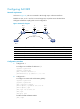
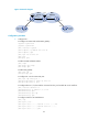
As shown in Figure 35, CEs are connected to PEs through Layer 3 Ethernet interfaces.
Establish an SVC, so CE 1 and CE 2 can exchange Layer 2 packets across the backbone.
Configure Soft GRE to simplify public tunnel configuration.
Figure 35 Network diagram
Device Interface IP address
Device
Interface IP address
CE 1 Eth1/1 100.1.1.1/24 CE 2 Eth1/1 100.1.1.2/24
PE 1 Loop0 192.2.2.2/32
P
Loop0
192.4.4.4/32
Eth1/2 10.1.1.1/24
Eth1/1
10.1.1.2/24
PE 2 Loop0 192.3.3.3/32 Eth1/2 10.2.2.2/24
Eth1/1 10.2.2.1/24
Configuration procedure
1. Configure CE 1:
# Configure an IP address for Ethernet 1/1.
<Sysname> system-view
[Sysname] sysname CE1
[CE1] interface ethernet 1/1
[CE1-Ethernet1/1] ip address 100.1.1.1 24
2. Configure PE 1:
# Configure an LSR ID and enable MPLS globally.
<Sysname> system-view
[Sysname] sysname PE1
[PE1] interface loopback 0
[PE1-LoopBack0] ip address 192.2.2.2 32
[PE1-LoopBack0] quit
[PE1] mpls lsr-id 192.2.2.2
[PE1] mpls
[PE1-mpls] quit
# Enable L2VPN and MPLS L2VPN.
[PE1] l2vpn
CE 1
CE 2
SVC
PE 1 PE 2P
Eth1/2
Eth1/1
Loop0 Loop0 Loop0
Eth1/1
Eth1/1
Eth1/2
Eth1/1
Eth1/2
Eth1/1