
R2511-HP MSR Router Series MPLS Configuration Guide(V5)


96
[PE1] display mpls static-l2vc interface ethernet 1/1
***CE-interface : Eth1/1 is up
VC State : up
Destination : 192.3.3.3
VC ID : --
Transmit-vpn-label : 100
Receive-vpn-label : 200
Tunnel Policy : -
Tunnel Type : SoftGRE
# Display detailed MPLS L2VPN PW information on PE 1.
[PE1] display mpls l2vpn fib pw vpws verbose
Total PW Entry:1
In Interface : Eth1/1
Service Instance ID : 0
In VC Label : 200
Out VC Label : 100
Out Interface : ----
Encapsulation Type : Ethernet
Entry Type : SoftGRE
MTU : 1500
Control Word : NO
Packets received : 0
Receives discarded : 0
Packets sent : 0
Sends discarded : 0
# Verify that CE 1 and CE 2 can ping each other when no public tunnel exists.
[CE1] ping 100.1.1.2
PING 100.1.1.2: 56 data bytes, press CTRL_C to break
Reply from 100.1.1.2: bytes=56 Sequence=0 ttl=255 time=51 ms
Reply from 100.1.1.2: bytes=56 Sequence=1 ttl=255 time=30 ms
Reply from 100.1.1.2: bytes=56 Sequence=2 ttl=255 time=36 ms
Reply from 100.1.1.2: bytes=56 Sequence=3 ttl=255 time=46 ms
Reply from 100.1.1.2: bytes=56 Sequence=4 ttl=255 time=30 ms
--- 100.1.1.2 ping statistics ---
5 packet(s) transmitted
5 packet(s) received
0.00% packet loss
round-trip min/avg/max = 30/38/51 ms
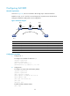
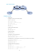
Configuring L2PT
Network requirements
As shown in Figure 36, CEs are connected to PEs through Layer 3 Ethernet interfaces.
Establish a Martini VC, so CE 1 and CE 2 can exchange Layer 2 packets across the backbone.
Configure L2PT to process the following Layer 2 protocol packets: