
R2511-HP MSR Router Series MPLS Configuration Guide(V5)


100
# Configure OSPF for LSP establishment.
[PE2] ospf
[PE2-ospf-1] area 0
[PE2-ospf-1-area-0.0.0.0] network 192.3.3.3 0.0.0.0
[PE2-ospf-1-area-0.0.0.0] network 10.2.2.0 0.0.0.255
[PE2-ospf-1-area-0.0.0.0] quit
[PE2-ospf-1] quit
# Configure a VC on Ethernet 1/1 (the interface connected to CE 2). The interface requires no IP
address.
[PE2] interface Ethernet1/1
[PE2-Ethernet1/1] mpls l2vc 192.2.2.2 101
[PE2-Ethernet1/1] quit
# Configure the L2PT destination multicast MAC address as 0110-cd10-10ac (the same as that
configured on PE 1).
[PE2] l2protocol-tunnel mac-address 0110-cd10-10ac
# Enable L2PT for STP, CDP, and GVRP on Ethernet 1/1 (the interface connected to CE 2).
[PE2]interface ethernet 1/1
[PE2-Ethernet1/1] l2protocol-tunnel stp tunnel
[PE2-Ethernet1/1] l2protocol-tunnel cdp experimental 3
[PE2-Ethernet1/1] l2protocol-tunnel gvrp drop
[PE2-Ethernet1/1] quit
5. Configure CE 2:
# Configure an IP address for Ethernet1/1.
<Sysname> system-view
[Sysname] sysname CE2
[CE2] interface ethernet 1/1
[CE2-Ethernet1/1] ip address 100.1.1.2 24
Verifying the configuration
# Execute the display l2protocol-tunnel command on PE 1 and PE 2 to display L2PT statistics.
Configuring L2PT and BPDU interoperation
Network requirements
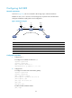
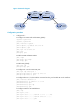
As shown in Figure 37, a service provider network consists of an MPLS network and a metro Ethernet. CE
1 and CE 2 are edges devices on the geographically dispersed network of a user. The customer networks
reside in VLAN 2. CE 1 and CE 2 implement consistent MSTP calculation across the service provider
network.
• Create a Martini VC within the MPLS network so CE 1 and CE 2 can exchange Layer 2 packets
across the MPLS network.
• Configure L2PT on PE 1. Enable BPDU tunneling on PE 3, and replace the destination MAC address
of STP packets with multicast MAC address 0100-0CCD-CDD0 to avoid packet conflict.
• Configure Ethernet 1/2 on PE 3 as an access port, and assign the port to VLAN 2.
• Configure Ethernet 1/2.2 on PE 2 to terminate packets from VLAN 2.
• Configure Ethernet 1/1 on PE 3 as a trunk port, and permit all VLANs to pass through the port.