
R2511-HP MSR Router Series MPLS Configuration Guide(V5)


101
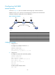
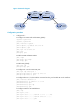
Figure 37 Network diagram
Configuration procedure
1. Configure PE 1:
# Configure an LSR ID and enable MPLS globally.
<Sysname> system-view
[Sysname] sysname PE1
[PE1] interface loopback 0
[PE1-LoopBack0] ip address 192.2.2.2 32
[PE1-LoopBack0] quit
[PE1] mpls lsr-id 192.2.2.2
[PE1] mpls
[PE1-mpls] quit
# Enable L2VPN and MPLS L2VPN.
[PE1] l2vpn
[PE1-l2vpn] mpls l2vpn
[PE1-l2vpn] quit
# Enable LDP globally.
[PE1] mpls ldp
[PE1-mpls-ldp] quit
# Configure PE 2 as the remote LDP peer.
[PE1] mpls ldp remote-peer 1
[PE1-mpls-ldp-remote-1] remote-ip 192.3.3.3
[PE1-mpls-ldp-remote-1] quit
# Configure Ethernet 1/2 (the interface connected to PE 2), and enable LDP on the interface.
[PE1] interface ethernet 1/2
[PE1-Ethernet1/2] ip address 10.1.1.1 24
[PE1-Ethernet1/2] mpls
[PE1-Ethernet1/2] mpls ldp
[PE1-Ethernet1/2] quit
# Configure OSPF for LSP establishment.
[PE1] ospf
[PE1-ospf-1] area 0
[PE1-ospf-1-area-0.0.0.0] network 10.1.1.1 0.0.0.255
[PE1-ospf-1-area-0.0.0.0] network 192.2.2.2 0.0.0.0
[PE1-ospf-1-area-0.0.0.0] quit
Customer
network
Metro
Ethernet
CE 1
CE 2
PE 1 PE 3PE 2
Eth1/2
10.1.1.1/24
Eth1/1
Loop0
192.2.2.2/32
Loop0
192.3.3.3/32
Eth1/1
Eth1/1
10.1.1.2/24
Eth1/2.2
Eth1/1
Eth1/2
Eth1/1
MPLS
network
Customer
network