
R2511-HP MSR Router Series MPLS Configuration Guide(V5)


177
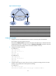
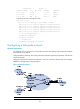
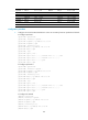
Figure 59 Network diagram
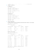
Device Interface IP address
Device
Interface
IP address
CE 1 Eth 1/1 10.1.1.1/24
P
POS 5/0
172.1.1.2/24
PE 1 Loop0 1.1.1.9/32 POS 5/1 172.2.1.1/24
Eth 1/1 10.1.1.2/24
PE 2
Loop0
2.2.2.9/32
POS 5/1 172.1.1.1/24
Eth 1/1
10.2.1.2/24
Tunnel0 20.1.1.1/24 POS 5/0 172.2.1.2/24
CE 2 Eth 1/1 10.2.1.1/24
Tunnel0
20.1.1.2/24
Configuration procedure
1. Configure an IGP on the MPLS backbone to ensure IP connectivity within the backbone:
This example uses OSPF. (Details not shown.)
# Execute the display ospf peer command to verify that OSPF adjacencies in Full state have been
established between PE 1, P, and PE 2. Execute the display ip routing-table command to verify that
the PEs have learned the loopback route of each other. (Details not shown.)
2. Configure basic MPLS on the PEs:
# Configure PE 1.
<PE1> system-view
[PE1] mpls lsr-id 1.1.1.9
[PE1] mpls
[PE1-mpls] quit
# Configure PE 2.
<PE2> system-view
[PE2] mpls lsr-id 2.2.2.9
[PE2] mpls
[PE2-mpls] quit
3. Configure VPN instances on PEs to allow CE access, and apply tunneling policies to the VPN
instances, using a GRE tunnel for VPN packet forwarding:
# Configure PE 1.
[PE1] tunnel-policy gre1
[PE1-tunnel-policy-gre1] tunnel select-seq gre load-balance-number 1
Loop0 Loop0
POS5/0 POS5/1
POS5/0POS5/1
Tunnel0
Tunnel0
Eth1/1Eth1/1
Eth1/1 Eth1/1
CE 1
CE 2
VPN 1
VPN 1
AS 65410 AS 65420
PE 1
PE 2
P
AS 100
GRE tunnel