
R2511-HP MSR Router Series MPLS Configuration Guide(V5)


189
Reply from 10.2.1.1: bytes=56 Sequence=5 ttl=250 time=2 ms
--- 10.2.1.1 ping statistics ---
5 packet(s) transmitted
5 packet(s) received
0.00% packet loss
round-trip min/avg/max = 2/2/3 ms
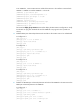
Configuring inter-AS option A
Network requirements
CE 1 and CE 2 belong to the same VPN. CE 1 accesses the network through PE 1 in AS 100 and CE 2
accesses the network through PE 2 in AS 200.
Inter-AS MPLS L3VPN is implemented using option A, where the VRF-to-VRF method is used to manage
VPN routes.
The MPLS backbone in each AS runs OSPF.
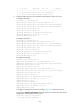
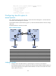
Figure 61 Network diagram
Device Interface IP address
Device
Interface IP address
CE 1 Eth 1/1 10.1.1.1/24 CE 2 Eth 1/1 10.2.1.1/24
PE 1 Loop0 1.1.1.9/32
PE 2
Loop0 4.4.4.9/32
Eth 1/1 10.1.1.2/24
Eth 1/1 10.2.1.2/24
POS 5/0 172.1.1.2/24 POS 5/0 162.1.1.2/24
A
SBR-PE 1 Loop0 2.2.2.9/32
A
SBR-PE 2
Loop0 3.3.3.9/32
POS 5/0 172.1.1.1/24
POS 5/0 162.1.1.1/24
POS 5/1 192.1.1.1/24 POS 5/1 192.1.1.2/24
Configuration procedure
1. Configure IGP on the MPLS backbone, implementing the connectivity in the backbone:
This example uses OSPF. Be sure to advertise the route to the 32-bit loopback interface address of
each router through OSPF. The loopback interface address of a router is to be used as the router's
LSR ID. (Details not shown.)