
R2511-HP MSR Router Series MPLS Configuration Guide(V5)

199
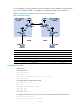
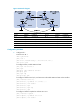
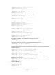
Figure 63 Network diagram
Device Interface IP address
Device
Interface IP address
PE 1 Loop0 2.2.2.9/32
PE 2
Loop0 5.5.5.9/32
Loop1 30.0.0.1/32 Loop1 20.0.0.1/32
S 2/0 1.1.1.2/8
S 2/0 9.1.1.2/8
A
SBR-PE 1 Loop0 3.3.3.9/32
A
SBR-PE 2
Loop0 4.4.4.9/32
S 2/0 1.1.1.1/8 S 2/0 9.1.1.1/8
S 2/1 11.0.0.2/8
S 2/1 11.0.0.1/8
Configuration procedure
1. Configure PE 1:
# Run IS-IS on PE 1.
<PE1> system-view
[PE1] isis 1
[PE1-isis-1] network-entity 10.1111.1111.1111.1111.00
[PE1-isis-1] quit
# Configure LSR ID, enable MPLS and LDP.
[PE1] mpls lsr-id 2.2.2.9
[PE1] mpls
[PE1-mpls] label advertise non-null
[PE1-mpls] quit
[PE1] mpls ldp
[PE1-mpls-ldp] quit
# Configure interface Serial 2/0, and start IS-IS and enable MPLS and LDP on the interface.
[PE1] interface serial 2/0
[PE1-Serial2/0] ip address 1.1.1.2 255.0.0.0
[PE1-Serial2/0] isis enable 1
[PE1-Serial2/0] mpls
[PE1-Serial2/0] mpls ldp
[PE1-Serial2/0] quit
# Configure interface Loopback 0 and start IS-IS on it.
[PE1] interface loopback 0
[PE1-LoopBack0] ip address 2.2.2.9 32
[PE1-LoopBack0] isis enable 1