
R2511-HP MSR Router Series MPLS Configuration Guide(V5)
206
[PE1-POS5/1] ip address 30.1.1.1 24
[PE1-POS5/1] isis enable 1
[PE1-POS5/1] mpls
[PE1-POS5/1] mpls ldp
[PE1-POS5/1] mpls ldp transport-address interface
[PE1-POS5/1] quit
[PE1] bgp 100
[PE1-bgp] peer 4.4.4.9 as-number 100
[PE1-bgp] peer 4.4.4.9 connect-interface loopback 0
[PE1-bgp] ipv4-family vpnv4
[PE1-bgp-af-vpnv4] peer 4.4.4.9 enable
[PE1-bgp-af-vpnv4] quit
[PE1-bgp] quit
# Configure PE 2 in the same way that PE 1 is configured. (Details not shown.)
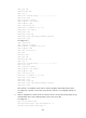
# On PE 1, verify that the LDP session between PE 1 and PE 2 has been established.
[PE1] display mpls ldp session
LDP Session(s) in Public Network
Total number of sessions: 1
----------------------------------------------------------------
Peer-ID Status LAM SsnRole FT MD5 KA-Sent/Rcv
----------------------------------------------------------------
4.4.4.9:0 Operational DU Active Off Off 378/378
----------------------------------------------------------------
LAM : Label Advertisement Mode FT : Fault Tolerance
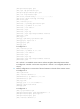
# On PE 1, verify that a BGP peer relationship in Established state has been established.
[PE1] display bgp peer
BGP local router ID : 3.3.3.9
Local AS number : 100
Total number of peers : 1 Peers in established state : 1
Peer AS MsgRcvd MsgSent OutQ PrefRcv Up/Down State
4.4.4.9 100 162 145 0 0 02:12:47 Established
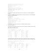
# On PE 1, verify that the IS-IS neighbor relationship has been set up.
[PE1] display isis peer
Peer information for ISIS(1)
----------------------------
System Id Interface Circuit Id State HoldTime Type PRI
0000.0000.0005 POS5/1 001 Up 29s L1L2 --
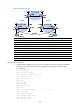
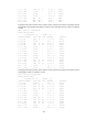
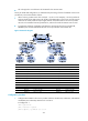
2. Configure the customer carrier network—start IS-IS as the IGP and enable LDP between PE 3 and
CE 1, and between PE 4 and CE 2.
# Configure PE 3.
<PE3> system-view
[PE3] interface loopback 0
[PE3-LoopBack0] ip address 1.1.1.9 32
[PE3-LoopBack0] quit
[PE3] mpls lsr-id 1.1.1.9
[PE3] mpls
[PE3-mpls] quit