
R2511-HP MSR Router Series MPLS Configuration Guide(V5)

212
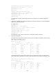
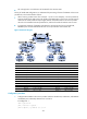
• CE 3 through CE 6 are CE devices of sub-VPNs for the customer VPN.
The key of nested VPN configuration is to understand the processing of routes of sub-VPNs on the service
provider PEs, which is described as follows:
• When receiving a VPNv4 route from a CE (CE 1 or CE 2 in this example), a service provider PE
replaces the RD of the VPNv4 route with the RD of the MPLS VPN on the service provider network
where the CE resides, adds the export target attribute of the MPLS VPN on the service provider
network to the extended community attribute list, and then forwards the VPNv4 route as usual.
• To implement exchange of sub-VPN routes between customer PEs and service provider PEs,
MP-EBGP peers must be established between service provider PEs and customer CEs.
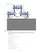
Figure 65 Network diagram
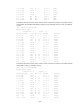
Device Interface IP address
Device
Interface
IP address
CE 1 Loop0 2.2.2.9/32 CE 2 Loop0 5.5.5.9/32
POS5/0 10.1.1.2/24
POS5/0
21.1.1.2/24
POS5/1 11.1.1.1/24
POS5/1
20.1.1.1/24
CE 3 Eth1/1 100.1.1.1/24 CE 4 Eth1/1 120.1.1.1/24
CE 5 Eth1/1 110.1.1.1/24
CE 6
Eth1/1
130.1.1.1/24
PE 1 Loop0 3.3.3.9/32
PE 2
Loop0
4.4.4.9/32
POS5/0 11.1.1.2/24 POS5/0 30.1.1.2/24
POS5/1 30.1.1.1/24
POS5/1
21.1.1.1/24
PE 3 Loop0 1.1.1.9/32
PE 4
Loop0
6.6.6.9/32
Eth1/1 100.1.1.2/24 Eth1/1 120.1.1.2/24
Eth1/2 110.1.1.2/24
Eth1/2
130.1.1.2/24
POS5/1 10.1.1.1/24
POS5/1
20.1.1.2/24
Configuration procedure
1. Configure MPLS L3VPN on the service provider backbone. Enable IS-IS, enable LDP, and establish
an MP-IBGP peer relationship between PE 1 and PE 2:
# Configure PE 1.
<PE1> system-view
[PE1] interface loopback 0
[PE1-LoopBack0] ip address 3.3.3.9 32
L
o
op
0
Loop0
L
oop0
Loop
0
L
o
o
p0