
R2511-HP MSR Router Series MPLS Configuration Guide(V5)
215
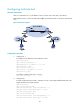
LDP and IS-IS neighbor relationships can be established between PE 3 and CE 1.
# Configure PE 4 and CE 2 in the same way that PE 3 and CE 1 are configured. (Details not
shown.)
3. Connect CE 1 and CE 2 to service provider PEs:
# Configure PE 1.
[PE1] ip vpn-instance vpn1
[PE1-vpn-instance-vpn1] route-distinguisher 200:1
[PE1-vpn-instance-vpn1] vpn-target 1:1
[PE1-vpn-instance-vpn1] quit
[PE1] interface pos 5/0
[PE1-POS5/0] ip binding vpn-instance vpn1
[PE1-POS5/0] ip address 11.1.1.2 24
[PE1-POS5/0] mpls
[PE1-POS5/0] quit
[PE1] bgp 100
[PE1-bgp] ipv4-family vpn-instance vpn1
[PE1-bgp-vpn1] peer 11.1.1.1 as-number 200
[PE1-bgp-vpn1] quit
[PE1-bgp] quit
# Configure CE 1.
[CE1] interface pos 5/1
[CE1-POS5/1] ip address 11.1.1.1 24
[CE1-POS5/1] mpls
[CE1-POS5/1] quit
[CE1] bgp 200
[CE1-bgp] peer 11.1.1.2 as-number 100
[CE1-bgp] import isis 2
[CE1-bgp] quit
# Configure PE 2 and CE 2 in the same way that PE 1 and CE 1 are configured. (Details not
shown.)
4. Connect sub-VPN CEs to the customer VPN PEs:
# Configure CE 3.
<CE3> system-view
[CE3] interface ethernet 1/1
[CE3-Ethernet1/1] ip address 100.1.1.1 24
[CE3-Ethernet1/1] quit
[CE3] bgp 65410
[CE3-bgp] peer 100.1.1.2 as-number 200
[CE3-bgp] import-route direct
[CE3-bgp] quit
# Configure CE 5.
<CE5> system-view
[CE5] interface ethernet 1/1
[CE5-Ethernet1/1] ip address 110.1.1.1 24
[CE5-Ethernet1/1] quit
[CE5] bgp 65411
[CE5-bgp] peer 110.1.1.2 as-number 200