
R2511-HP MSR Router Series MPLS Configuration Guide(V5)

221
Configuring multi-role host
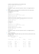
Network requirements
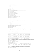
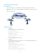
Host A is connected to CE 1. Its IP address is 100.1.1.2 and it can access VPN 1 and VPN 2.
Bind interface Serial 2/1 of PE 1 to VPN instance vpn1, and interface Serial 2/1 of PE 2 to VPN instance
vpn2.
Figure 66 Network diagram
Configuration procedure
1. Configure CE 1:
# Configure the IP addresses of the interfaces on CE 1.
<CE1> system-view
[CE1] interface ethernet 1/1
[CE1-Ethernet1/1] ip address 100.1.1.1 24
[CE1-Ethernet1/1] quit
[CE1] interface serial 2/0
[CE1-Serial2/0] ip address 1.1.1.2 24
[CE1-Serial2/0] quit
# Configure a default route to PE 1 on CE 1.
[CE1] ip route-static 0.0.0.0 0 1.1.1.1
2. Configure PE 1:
# Create a VPN instance for VPN 1 and VPN 2 on PE 1 and configure different RDs and route
targets attributes for the VPN instances.
<PE1> system-view
[PE1] ip vpn-instance vpn1
[PE1-vpn-instance-vpn1] route-distinguisher 100:1
[PE1-vpn-instance-vpn1] vpn-target 100:1 both
[PE1-vpn-instance-vpn1] quit
[PE1] ip vpn-instance vpn2
[PE1-vpn-instance-vpn2] route-distinguisher 100:2
[PE1-vpn-instance-vpn2] vpn-target 100:2 both