
R2511-HP MSR Router Series MPLS Configuration Guide(V5)

223
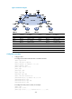
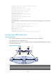
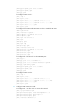
Figure 67 Network diagram
Device Interface IP address
Device
Interface
IP address
CE 1 Eth 1/1 10.2.1.1/24
CE 3
Eth 1/1
10.1.1.1/24
CE 2 Eth 1/1 10.4.1.1/24 CE 4 Eth 1/1 10.3.1.1/24
UPE 1 Loop0 1.1.1.9/32
UPE 2
Loop0
4.4.4.9/32
Eth 1/1 10.2.1.2/24
Eth 1/1
172.2.1.1/24
Eth 1/2 10.4.1.2/24 Eth 1/2 10.1.1.2/24
Eth 1/3 172.1.1.1/24
Eth 1/3
10.3.1.2/24
SPE 1 Loop0 2.2.2.9/32
SPE 2
Loop0
3.3.3.9/32
Eth 1/1 172.1.1.2/24 Eth 1/1 180.1.1.2/24
Eth 1/2 180.1.1.1/24
Eth 1/2
172.2.1.2/24
Configuration procedure
1. Configure UPE 1:
# Configure basic MPLS and MPLS LDP to establish LDP LSPs.
<UPE1> system-view
[UPE1] interface loopback 0
[UPE1-LoopBack0] ip address 1.1.1.9 32
[UPE1-LoopBack0] quit
[UPE1] mpls lsr-id 1.1.1.9
[UPE1] mpls
[UPE1-mpls] quit
[UPE1] mpls ldp
[UPE1-mpls-ldp] quit
[UPE1] interface ethernet 1/3
[UPE1-Ethernet1/3] ip address 172.1.1.1 24
[UPE1-Ethernet1/3] mpls
[UPE1-Ethernet1/3] mpls ldp
[UPE1-Ethernet1/3] quit
# Configure the IGP protocol, OSPF, for example.
[UPE1] ospf
[UPE1-ospf-1] area 0
[UPE1-ospf-1-area-0.0.0.0] network 172.1.1.0 0.0.0.255