
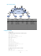
R2511-HP MSR Router Series MPLS Configuration Guide(V5)
232
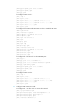
[PE1-Ethernet1/1] ip binding vpn-instance vpn1
[PE1-Ethernet1/1] ip address 100.1.1.2 24
[PE1-Ethernet1/1] quit
[PE1] ospf 100 vpn-instance vpn1
[PE1-ospf-100] domain-id 10
[PE1-ospf-100] area 1
[PE1-ospf-100-area-0.0.0.1] network 100.1.1.0 0.0.0.255
[PE1-ospf-100-area-0.0.0.1] quit
[PE1-ospf-100] quit
[PE1] bgp 100
[PE1-bgp] ipv4-family vpn-instance vpn1
[PE1-bgp-vpn1] import-route ospf 100
[PE1-bgp-vpn1] import-route direct
[PE1-bgp-vpn1] quit
[PE1-bgp] quit
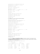
# Configure PE 2 to allow CE 2 to access the network.
[PE2] ip vpn-instance vpn1
[PE2-vpn-instance-vpn1] route-distinguisher 100:2
[PE2-vpn-instance-vpn1] vpn-target 1:1
[PE2-vpn-instance-vpn1] quit
[PE2] interface ethernet 1/1
[PE2-Ethernet1/1] ip binding vpn-instance vpn1
[PE2-Ethernet1/1] ip address 120.1.1.2 24
[PE2-Ethernet1/1] quit
[PE2] ospf 100 vpn-instance vpn1
[PE2-ospf-100] domain-id 10
[PE2-ospf-100] area 1
[PE2-ospf-100-area-0.0.0.1] network 120.1.1.0 0.0.0.255
[PE2-ospf-100-area-0.0.0.1] quit
[PE2-ospf-100] quit
[PE2] bgp 100
[PE2-bgp] ipv4-family vpn-instance vpn1
[PE2-bgp-vpn1] import-route ospf 100
[PE2-bgp-vpn1] import-route direct
[PE2-bgp-vpn1] quit
[PE2-bgp] quit
# Execute the display ip routing-table vpn-instance command on the PEs. This example uses PE 1
to verify that the path to the peer CE is along the OSPF route across the customer networks, instead
of the BGP route across the backbone.
[PE1] display ip routing-table vpn-instance vpn1
Routing Tables: vpn1
Destinations : 5 Routes : 5
Destination/Mask Proto Pre Cost NextHop Interface
20.1.1.0/24 OSPF 10 1563 100.1.1.1 Eth1/1
30.1.1.0/24 OSPF 10 3125 100.1.1.1 Eth1/1
100.1.1.0/24 Direct 0 0 100.1.1.2 Eth1/1
100.1.1.2/32 Direct 0 0 127.0.0.1 InLoop0
120.1.1.0/24 OSPF 10 3126 100.1.1.1 Eth1/1