
R2511-HP MSR Router Series MPLS Configuration Guide(V5)
233
4. Configure a sham link:
# Configure PE 1.
[PE1] interface loopback 1
[PE1-LoopBack1] ip binding vpn-instance vpn1
[PE1-LoopBack1] ip address 3.3.3.3 32
[PE1-LoopBack1] quit
[PE1] ospf 100
[PE1-ospf-100] area 1
[PE1-ospf-100-area-0.0.0.1] sham-link 3.3.3.3 5.5.5.5 cost 10
[PE1-ospf-100-area-0.0.0.1] quit
[PE1-ospf-100] quit
# Configure PE 2.
[PE2] interface loopback 1
[PE2-LoopBack1] ip binding vpn-instance vpn1
[PE2-LoopBack1] ip address 5.5.5.5 32
[PE2-LoopBack1] quit
[PE2] ospf 100
[PE2-ospf-100] area 1
[PE2-ospf-100-area-0.0.0.1] sham-link 5.5.5.5 3.3.3.3 cost 10
[PE2-ospf-100-area-0.0.0.1] quit
[PE2-ospf-100] quit
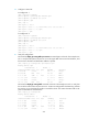
5. Verify the configuration:
# Execute the display ip routing-table vpn-instance command again on the PEs. This example uses
PE 1 to verify that the path to the peer CE is now along the BGP route across the backbone, and
that a route to the sham link destination address is present.
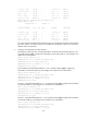
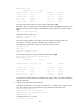
[PE1] display ip routing-table vpn-instance vpn1
Routing Tables: vpn1
Destinations : 6 Routes : 6
Destination/Mask Proto Pre Cost NextHop Interface
3.3.3.3/32 Direct 0 0 127.0.0.1 InLoop0
5.5.5.5/32 BGP 255 0 2.2.2.9 NULL0
20.1.1.0/24 OSPF 10 1563 100.1.1.1 Eth1/1
100.1.1.0/24 Direct 0 0 100.1.1.2 Eth1/1
100.1.1.2/32 Direct 0 0 127.0.0.1 InLoop0
120.1.1.0/24 BGP 255 0 2.2.2.9 NULL0
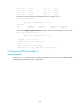
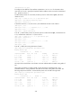
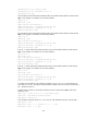
# Execute the display ip routing-table command on the CEs. This example uses CE 1 to verify that
the cost of the OSPF route to the peer CE is now 10 (the cost configured for the sham link), and that
the next hop is now the Ethernet interface connected to the PE. This means that VPN traffic to the
peer is forwarded over the backbone.
[CE1] display ip routing-table
Routing Tables: Public
Destinations : 9 Routes : 9
Destination/Mask Proto Pre Cost NextHop Interface
20.1.1.0/24 Direct 0 0 20.1.1.1 S2/1
20.1.1.1/32 Direct 0 0 127.0.0.1 InLoop0
20.1.1.2/32 Direct 0 0 20.1.1.2 S2/1
30.1.1.0/24 OSPF 10 1574 100.1.1.2 Eth1/1
100.1.1.0/24 Direct 0 0 100.1.1.1 Eth1/1