
R2511-HP MSR Router Series MPLS Configuration Guide(V5)

239
Now, the routing information for the two VPNs has been redistributed into the routing tables on PE
1.
Configuring MCE (example 2)
Network requirements
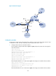
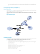
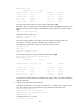
As shown in Figure 70, an MCE is connected to VPN 1 through VLAN-interface 10 and is connected with
VPN 2 through VLAN-interface 20. RIP runs in VPN 2.
Configure the MCE to separate routes for different VPNs and advertise the VPN routes to PE 1 through
OSPF.
Figure 70 Network diagram
Configuration procedure
Assume that the system name of the MCE device is MCE, the system names of the edge devices of VPN
1 and VPN 2 are VR1 and VR2, respectively, and the system name of PE 1 is PE1.
1. Configure the VPN instances on the MCE and PE 1:
# On the MCE, configure VPN instances vpn1 and vpn2, and specify an RD and route targets for
each VPN instance.
<MCE> system-view
[MCE] ip vpn-instance vpn1
[MCE-vpn-instance-vpn1] route-distinguisher 10:1
[MCE-vpn-instance-vpn1] vpn-target 10:1
[MCE-vpn-instance-vpn1] quit
[MCE] ip vpn-instance vpn2