
R2511-HP MSR Router Series MPLS Configuration Guide(V5)


243
[MCE-ospf-10] import-route static
# On PE 1, start OSPF process 10, bind the process to VPN instance vpn1, set the domain ID to 10,
and advertise subnet 30.1.1.0 in area 0.
[PE1] ospf 10 router-id 100.100.10.1 vpn-instance vpn1
[PE1-ospf-10] domain-id 10
[PE1-ospf-10] area 0
[PE1-ospf-10-area-0.0.0.0] network 30.1.1.0 0.0.0.255
[PE1-ospf-10-area-0.0.0.0] quit
[PE1-ospf-10] quit
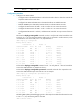
# On PE 1, display the routing table of VPN1.
[PE1] display ip routing-table vpn-instance vpn1
Routing Tables: vpn1
Destinations : 5 Routes : 5
Destination/Mask Proto Pre Cost NextHop Interface
30.1.1.0/24 Direct 0 0 30.1.1.2 Vlan30
30.1.1.2/32 Direct 0 0 127.0.0.1 InLoop0
127.0.0.0/8 Direct 0 0 127.0.0.1 InLoop0
127.0.0.1/32 Direct 0 0 127.0.0.1 InLoop0
192.168.0.0/24 O_ASE 150 1 30.1.1.1 Vlan30
The output shows that the static route of VPN 1 has been redistributed to the OSPF routing table of
PE 1.
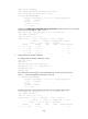
Take similar procedures to configure OSPF process 20 between MCE and PE 1 and redistribute
VPN 2's routing information from RIP into the OSPF routing table of MCE. The following output
shows that PE 1 has learned the private route of VPN 2 through OSPF.
[PE1] display ip routing-table vpn-instance vpn2
Routing Tables: vpn2
Destinations : 5 Routes : 5
Destination/Mask Proto Pre Cost NextHop Interface
40.1.1.0/24 Direct 0 0 40.1.1.2 Vlan40
40.1.1.2/32 Direct 0 0 127.0.0.1 InLoop0
127.0.0.0/8 Direct 0 0 127.0.0.1 InLoop0
127.0.0.1/32 Direct 0 0 127.0.0.1 InLoop0
192.168.10.0/24 O_ASE 150 1 40.1.1.1 Vlan40
The routing information for the two VPNs has been redistributed into the routing tables on PE 1.
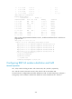
Configuring MCE (example 3)
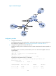
Network requirements
As shown in Figure 71, configure the MCE to advertise the routes of VPNs 1 and 2 to PE 1, so that the sites
of each VPN can communicate with each other over the MPLS backbone.
Run OSPF in both VPN 1 and VPN 2. Run EBGP between the MCE and PE 1.