
R2511-HP MSR Router Series MPLS Configuration Guide(V5)


246
172.16.10.0/24 BGP 255 2 30.1.1.1 Vlan30
# Perform similar configuration on the MCE and PE 1 for VPN 2. Redistribute the OSPF routes of
VPN instance vpn2 into the EBGP routing table. (Details not shown.)
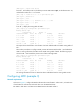
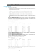
The following output shows that PE 1 has learned the private route of VPN 2 through BGP:
[PE1] display ip routing-table vpn-instance vpn2
Routing Tables: vpn2
Destinations : 5 Routes : 5
Destination/Mask Proto Pre Cost NextHop Interface
40.1.1.0/24 Direct 0 0 40.1.1.2 Vlan40
40.1.1.2/32 Direct 0 0 127.0.0.1 InLoop0
127.0.0.0/8 Direct 0 0 127.0.0.1 InLoop0
127.0.0.1/32 Direct 0 0 127.0.0.1 InLoop0
172.16.20.0/24 BGP 255 2 40.1.1.1 Vlan40
The MCE has redistributed the OSPF routes of the two VPN instances into the EBGP routing tables
of PE 1.
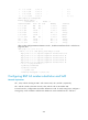
Configuring BGP AS number substitution
Network requirements
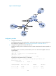
As shown in Figure 72, CE 1 and CE 2 belong to VPN 1 and are connected to PE 1 and PE 2, respectively.
In addition, they use the same AS number 600.
Figure 72 Network diagram
Device Interface IP address Device Interface IP address
CE 1 Eth 1/1 10.1.1.1/24
P
Loop0
2.2.2.9/32
Eth 1/2 100.1.1.1/24
Eth 1/1
20.1.1.2/24
PE 1 Loop0 1.1.1.9/32 Eth 1/2 30.1.1.1/24
Eth 1/1 10.1.1.2/24
PE 2
Loop0
3.3.3.9/32
Eth 1/2 20.1.1.1/24
Eth 1/1
10.2.1.2/24
CE 2 Eth 1/1 10.2.1.1/24 Eth 1/2 30.1.1.2/24
Loop0
Loop0 Loop0
PE 1
P
PE 2
CE 1
CE 2
VPN 1
AS 600
VPN 1
AS 600
Eth1/2
Eth1/2
Eth1/2
Eth1/2Eth1/2
Eth1/1
Eth1/1
Eth1/1
Eth1/1
Eth1/1
MPLS backbone
AS 100