
R2511-HP MSR Router Series MPLS Configuration Guide(V5)


247
Eth 1/2 200.1.1.1/24
Configuration procedure
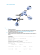
1. Configure basic MPLS L3VPN:
{ Configure OSPF on the MPLS backbone to allow the PEs and P device to learn the routes of the
loopback interfaces from each other.
{ Configure basic MPLS and MPLS LDP on the MPLS backbone to establish LDP LSPs.
{ Establish MP-IBGP peer relationship between the PEs to advertise VPN IPv4 routes.
{ Configure the VPN instance of VPN 1 on PE 2 to allow CE 2 to access the network.
{ Configure the VPN instance of VPN 1 on PE 1 to allow CE 1 to access the network.
{ Configure BGP between PE 1 and CE 1, and between PE 2 and CE 2 to inject routes of CEs into
PEs.
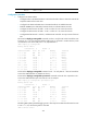
# Execute the display ip routing-table command on CE 2 to verify that CE 2 has learned the route
to network 10.1.1.0/24, where the interface used by CE 1 to access PE 1 resides. However, it has
not learned the route to the VPN (100.1.1.0/24) behind CE 1.
<CE2> display ip routing-table
Routing Tables: Public
Destinations : 8 Routes : 8
Destination/Mask Proto Pre Cost NextHop Interface
10.1.1.0/24 BGP 255 0 10.2.1.2 Eth1/1
10.1.1.1/32 BGP 255 0 10.2.1.2 Eth1/1
10.2.1.0/24 Direct 0 0 10.2.1.1 Eth1/1
10.2.1.1/32 Direct 0 0 127.0.0.1 InLoop0
10.2.1.2/32 Direct 0 0 10.2.1.2 Eth1/1
127.0.0.0/8 Direct 0 0 127.0.0.1 InLoop0
127.0.0.1/32 Direct 0 0 127.0.0.1 InLoop0
200.1.1.0/24 Direct 0 0 200.1.1.1 InLoop0
200.1.1.1/32 Direct 0 0 127.0.0.1 InLoop0
# Execute the display ip routing-table command on CE 1 to verify that CE 1 has not learned the
route to the VPN behind CE 2. (Details not shown.)
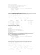
# Execute the display ip routing-table vpn-instance command on the PEs. The output shows the
route to the VPN behind the peer CE. Take PE 2 as an example:
<PE2> display ip routing-table vpn-instance vpn1
Routing Tables: vpn1
Destinations : 7 Routes : 7
Destination/Mask Proto Pre Cost NextHop Interface
10.1.1.0/24 BGP 255 0 1.1.1.9 NULL0
10.1.1.1/32 BGP 255 0 1.1.1.9 NULL0
10.2.1.0/24 Direct 0 0 10.2.1.2 Eth1/1
10.2.1.1/32 Direct 0 0 10.2.1.1 Eth1/1
10.2.1.2/32 Direct 0 0 127.0.0.1 InLoop0
100.1.1.1/32 BGP 255 0 1.1.1.9 NULL0
200.1.1.1/32 BGP 255 0 10.2.1.1 Eth1/1
# Enabling BGP update packet debugging on PE 2. The output shows that PE 2 advertises the route
to 100.1.1.1/32, and the AS_PATH is 100 600.
<PE2> terminal monitor