
R2511-HP MSR Router Series MPLS Configuration Guide(V5)


250
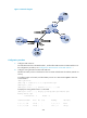
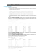
Figure 73 Network diagram
Device Interface IP address
Device
Interface
IP address
CE 1 Loop0 100.1.1.1/32 CE 3 Loop0 200.1.1.1/32
Eth1/1 10.1.1.1/24
Eth1/1
10.3.1.1/24
CE 2 Eth1/1 10.2.1.1/24
PE 2
Loop0
2.2.2.9/32
PE 1 Loop0 1.1.1.9/32 Eth1/1 10.2.1.2/24
Eth1/1 10.1.1.2/24
Eth1/2
40.1.1.1/24
Eth1/2 20.1.1.1/24
Eth1/3
20.1.1.2/24
Eth1/3 30.1.1.1/24 P Loop0 3.3.3.9/32
PE 3 Loop0 4.4.4.9/32
Eth1/1
30.1.1.2/24
Eth1/1 10.3.1.2/24
Eth1/2
40.1.1.2/24
Eth1/2 50.1.1.2/24 Eth1/3 50.1.1.1/24
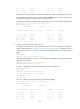
Configuration procedure
1. Configure basic MPLS L3VPN:
{ Configure OSPF on the MPLS backbone to allow the PEs and P device to learn the routes of the
loopback interfaces from each other.
{ Configure basic MPLS and MPLS LDP on the MPLS backbone to establish LDP LSPs.
{ Establish MP-IBGP peer relationships between the PEs to advertise VPN IPv4 routes.
{ Configure VPN 1 on PE 1 to allow CE 1 to access the network.
{ Configure VPN 1 on PE 2 to allow CE 2 to access the network.
{ Configure VPN 1 on PE 3 to allow CE 3 to access the network.
{ Configure BGP between PE 1 and CE 1, between PE 2 and CE 2, and between PE 3 and CE 3
to inject routes of CEs into PEs.
2. Configure BGP AS number substitution:
# Configure BGP AS number substitution on PE 1, PE2, and PE3 as described in "Configuring BGP
AS number substitution."
Loop0
Loop0
Loop0
PE 1
P
PE 3
CE 2
CE 3
VPN 1
AS 600
VPN 1
AS 600
Eth1/2
Eth1/2
Eth1/3
Eth1/1
Eth1/1
Eth1/1
Eth1/1
Eth1/1
MPLS backbone
AS 100
CE 1
Eth1/1
Eth1/1
Loop0
Eth1/2
Eth1/3
Eth1/3
Eth1/2
PE 2
Loop0
Loop0