
R2511-HP MSR Router Series MPLS Configuration Guide(V5)

283
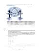
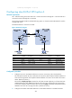
Configure tunneling policies on the PEs and specify the tunnel type for VPN traffic as GRE.
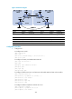
Figure 77 Network diagram
Device Interface IP address
Device
Interface
IP address
CE 1 Eth1/1 2001:1::1/96
P
POS5/0
172.1.1.2/24
PE 1 Loop0 1.1.1.9/32 POS5/1 172.2.1.1/24
Eth1/1 2001:1::2/96
PE 2
Loop0
2.2.2.9/32
POS5/1 172.1.1.1/24
Eth1/1
2001:2::2/96
Tunnel0 20.1.1.1/24 POS5/0 172.2.1.2/24
CE 2 Eth1/1 2001:2::1/96
Tunnel0
20.1.1.2/24
Configuration procedure
1. Configure an IGP on the MPLS backbone to ensure IP connectivity among the PEs and the P router:
This example uses OSPF. (Details not shown.)
# Execute the display ospf peer command to verify that OSPF adjacencies in Full state have been
established between PE 1, P, and PE 2. Execute the display ip routing-table command to verify that
the PEs have learned the routes to the loopback interfaces of each other. (Details not shown.)
2. Configure basic MPLS on the PEs:
# Configure PE 1.
<PE1> system-view
[PE1] mpls lsr-id 1.1.1.9
[PE1] mpls
[PE1-mpls] quit
# Configure PE 2.
<PE2> system-view
[PE2] mpls lsr-id 2.2.2.9
[PE2] mpls
[PE2-mpls] quit
3. Configure VPN instances on the PEs to allow CE access, and apply tunneling policies to the VPN
instances to use a GRE tunnel for VPN packet forwarding:
# Configure PE 1.