
R2511-HP MSR Router Series MPLS Configuration Guide(V5)


310
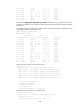
Take similar procedures to configure OSPFv3 process 20 between the MCE and PE 1 and
redistribute VPN 2's routes from RIPng process 20 into the OSPFv3 routing table of the MCE. The
following output shows that PE 1 has learned the private route of VPN 2 through OSPFv3.
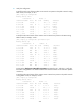
[PE1] display ipv6 routing-table vpn-instance vpn2
Routing Table :
Destinations : 5 Routes : 5
Destination: ::1/128 Protocol : Direct
NextHop : ::1 Preference: 0
Interface : InLoop0 Cost : 0
Destination: 2002:2::/64 Protocol : Direct
NextHop : 2002:2::4 Preference: 0
Interface : Eth1/1.2 Cost : 0
Destination: 2002:2::4/128 Protocol : Direct
NextHop : ::1 Preference: 0
Interface : InLoop0 Cost : 0
Destination: 2012::/64 Protocol : OSPFv3
NextHop : FE80::200:5EFF:FE01:1C06 Preference: 15
Interface : Eth1/1.2 Cost : 10
Destination: FE80::/10 Protocol : Direct
NextHop : :: Preference: 0
Interface : NULL0 Cost : 0
The routing information for the two VPNs has been redistributed into the routing tables on PE 1.
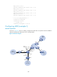
Configuring MCE (example 2)
Network requirements
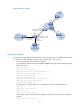
As shown in Figure 82, an MCE is connected to VPN 1 through VLAN-interface 10 and to VPN 2 through
VLAN-interface 20. RIPng is used in VPN 2.
Configure the MCE to separate routes for different VPNs and advertise VPN routes to PE 1 through
OSPFv3.