
R2511-HP MSR Router Series MPLS Configuration Guide(V5)
363
------------------------------------------------------------------
FEC In/Out Label In/Out IF Vrf Name
-/- 20/30 Eth1/1/Eth1/2
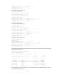
[RouterC] display mpls lsp
------------------------------------------------------------------
LSP Information: STATIC CRLSP
------------------------------------------------------------------
FEC In/Out Label In/Out IF Vrf Name
-/- 30/NULL Eth1/1/-
[RouterA] display mpls static-cr-lsp
total statics-cr-lsp : 1
Name FEC I/O Label I/O If State
Tunnel0 3.3.3.3/32 NULL/20 -/Eth1/1 Up
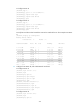
[RouterB] display mpls static-cr-lsp
total statics-cr-lsp : 1
Name FEC I/O Label I/O If State
Tunnel0 -/- 20/30 Eth1/1/Eth1/2 Up
[RouterC] display mpls static-cr-lsp
total statics-cr-lsp : 1
Name FEC I/O Label I/O If State
Tunnel0 -/- 30/NULL Eth1/1/- Up
On an MPLS TE tunnel configured using a static CR-LSP, traffic is forwarded directly based on label
at the transit nodes and egress node. Therefore, it is normal that the FEC field in the output is empty
on Router B and Router C.
7. Create a static route to direct traffic to the MPLS TE tunnel:
[RouterA] ip route-static 3.2.1.2 24 tunnel 0 preference 1
# Execute the display ip routing-table command on Router A. The output shows a static route entry
with interface Tunnel0 as the outgoing interface.
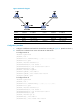
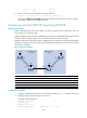
Configuring MPLS TE tunnel using RSVP-TE
Network requirements
Router A, Router B, Router C, and Router D are running IS-IS and all of them are Level-2 routers.
Use RSVP-TE to create a TE tunnel with 2000 kbps of bandwidth from Router A to Router D, making sure
that the maximum bandwidth of each link that the tunnel traverses is 10000 kbps and the maximum
reservable bandwidth is 5000 kbps.