
R2511-HP MSR Router Series MPLS Configuration Guide(V5)

370
3 4.4.4.9 ISIS 1 Level-2 1
4 1.1.1.9 ISIS 1 Level-2 1
8. Create a static route to direct traffic to the MPLS TE tunnel:
[RouterA] ip route-static 30.1.1.2 24 tunnel 1 preference 1
# Execute the display ip routing-table command on Router A. The output shows a static route entry
with interface Tunnel1 as the outgoing interface.
Configuring inter-AS MPLS TE tunnel using RSVP-TE
Network requirements
Router A and Router B are in AS 100, and they run OSPF as the IGP. Router C and Router D are in AS
200, and they run OSPF as the IGP.
Establish an EBGP connection between ASBRs Router B and Router C. Redistribute BGP routes into OSPF
and OSPF routes into BGP, so that a route is available between AS 100 and AS 200.
Establish an MPLS TE tunnel between Router A and Router D by using RSVP-TE, with the bandwidth being
2000 kbps. Along the tunnel, set the maximum link bandwidth to 10000 kbps and maximum reservable
bandwidth to 5000 kbps.
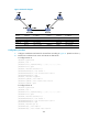
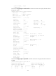
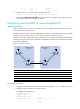
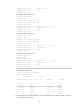
Figure 94 Network diagram
Device Interface IP address
Device
Interface
IP address
Router A Loop0 1.1.1.9/32 Router C Loop0 3.3.3.9/32
Eth1/1 10.1.1.1/24
Eth1/1
30.1.1.1/24
Router B Loop0 2.2.2.9/32
POS5/0
20.1.1.2/24
Eth1/1 10.1.1.2/24 Router D Loop0 4.4.4.9/32
POS5/0 20.1.1.1/24
Eth1/1
30.1.1.2/24
Configuration procedure
1. Configure IP addresses and masks for the interfaces according to Figure 94. (Details not shown.)
2. Configure OSPF to advertise routes within the ASs:
# Configure OSPF on Router A.
<RouterA> system-view
[RouterA] ospf
[RouterA-ospf-1] area 0
[RouterA-ospf-1-area-0.0.0.0] network 10.1.1.0 0.0.0.255
Eth1/1
Eth1/1
POS5/0 POS5/0
Eth1/1
Eth1/1
Loop0
Loop0
Loop0 Loop0
Router A
Router B
Router C
Router D
MPLS backbone
AS 100
MPLS backbone
AS 200