
R2511-HP MSR Router Series MPLS Configuration Guide(V5)

377
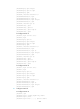
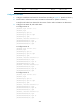
# Execute the display ip routing-table command on Router A. The output shows a static route entry
with interface Tunnel 1 as the outgoing interface.
[RouterA] display ip routing-table
Routing Tables: Public
Destinations : 14 Routes : 14
Destination/Mask Proto Pre Cost NextHop Interface
1.1.1.9/32 Direct 0 0 127.0.0.1 InLoop0
2.2.2.9/32 OSPF 10 1 10.1.1.2 Eth1/1
3.3.3.9/32 O_ASE 150 1 10.1.1.2 Eth1/1
4.4.4.9/32 O_ASE 150 1 10.1.1.2 Eth1/1
7.1.1.0/24 Direct 0 0 7.1.1.1 Tun1
7.1.1.1/32 Direct 0 0 127.0.0.1 InLoop0
10.1.1.0/24 Direct 0 0 10.1.1.1 Eth1/1
10.1.1.1/32 Direct 0 0 127.0.0.1 InLoop0
20.1.1.0/24 O_ASE 150 1 10.1.1.2 Eth1/1
30.1.1.0/24 Static 1 0 7.1.1.1 Tun1
127.0.0.0/8 Direct 0 0 127.0.0.1 InLoop0
127.0.0.1/32 Direct 0 0 127.0.0.1 InLoop0
Configuring RSVP-TE GR
Network requirements
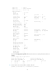
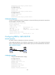
Router A, Router B and Router C are running IS-IS. All of them are Level-2 devices and support RSVP hello
extension.
Use RSVP-TE to create a TE tunnel from Router A to Router C.
Router A, Router B and Router C are RSVP-TE neighbors. Configure the RSVP-TE GR on the routers, so
each of them can provide GR helper support when another is GR restarting.
Figure 95 Network diagram
Configuration procedure
1. Configure IP addresses and masks for the interfaces according to Figure 95. (Details not shown.)
2. Enable IS-IS to advertise host routes with LSR IDs as destinations. (Details not shown.)
3. Configure basic MPLS TE, and enable RSVP-TE and RSVP hello extension:
# Configure Router A.
<RouterA> system-view
[RouterA] mpls lsr-id 1.1.1.9
[RouterA] mpls